
Optical waiting type plane imaging system for framing, scanning and simultaneous recording

A plane imaging and framing technology, applied in the field of framing scanning imaging systems, can solve the problems of difficulty in time synchronization and speed, different time bases, low spatial resolution, etc., and achieve high time-bandwidth product and high interpretation accuracy. The effect of high accuracy and high interpretation accuracy

Active Publication Date: 2010-03-10
SHENZHEN UNIV
View PDF0 Cites 11 Cited by
  • Summary
  • Abstract
  • Description
  • Claims
  • Application Information

AI Technical Summary

Problems solved by technology

Therefore, although the entire recorder uses only one camera, which is an improvement compared to the early framing and scanning simultaneous recorder, it is still difficult to achieve due to the existence of two sets of rotating mirror systems with different system time references. Precise time synchronization and consistent speed
Afterwards, the United States studied recorders with a common space reference and a common time reference, but these recorders used a spatial beam optical system with low spatial resolution and a complex system structure (Manfred Held. Simultaneously Gained Streak and Framing Records Offer a Great Advantage in the Field of Detonics. Propellants, Explosives, Pyrotechnics, 2001, 26: 148-155)

Method used


Image

  • Optical waiting type plane imaging system for framing, scanning and simultaneous recording
  • Optical waiting type plane imaging system for framing, scanning and simultaneous recording

Examples


Embodiment Construction

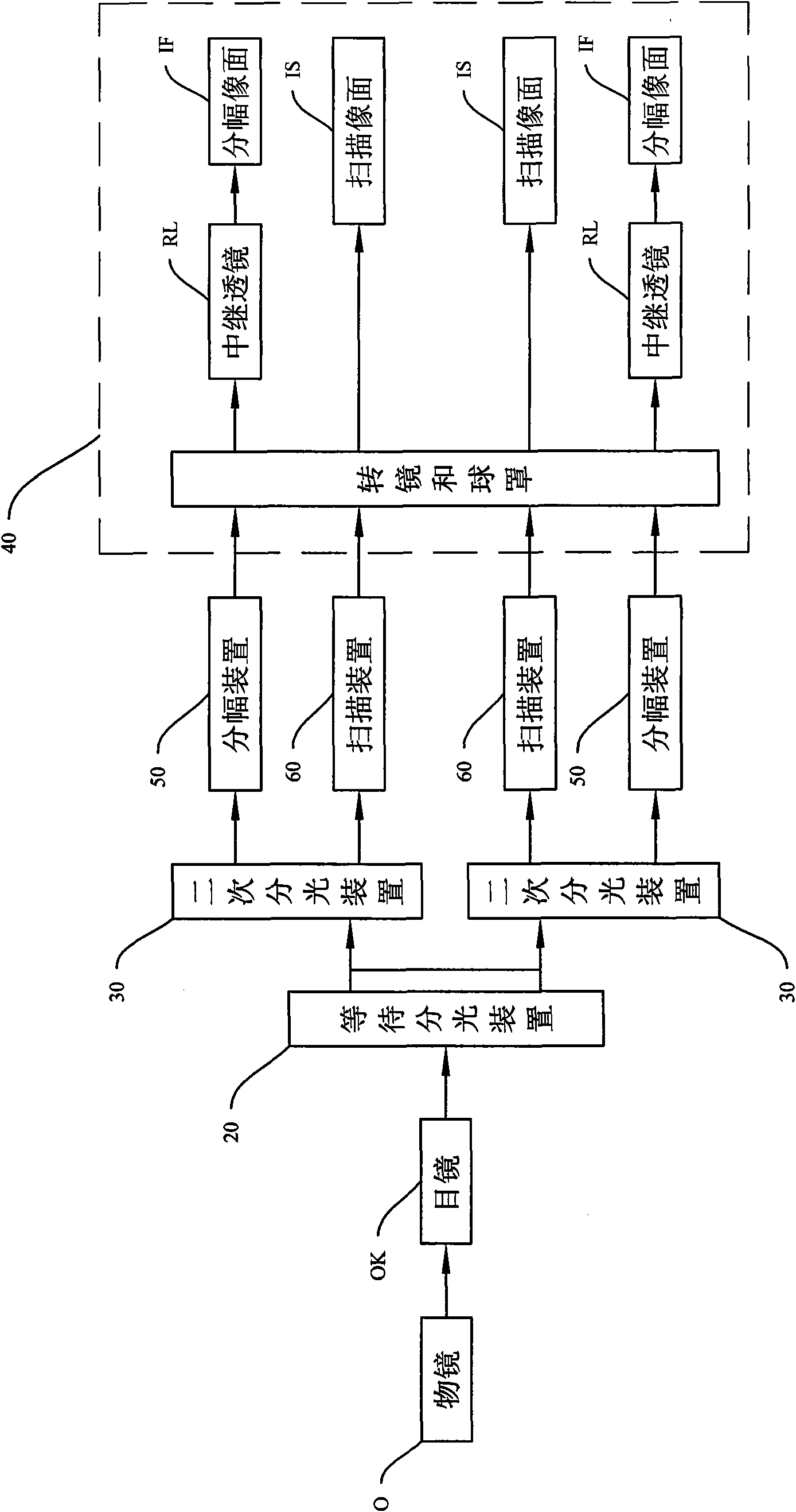
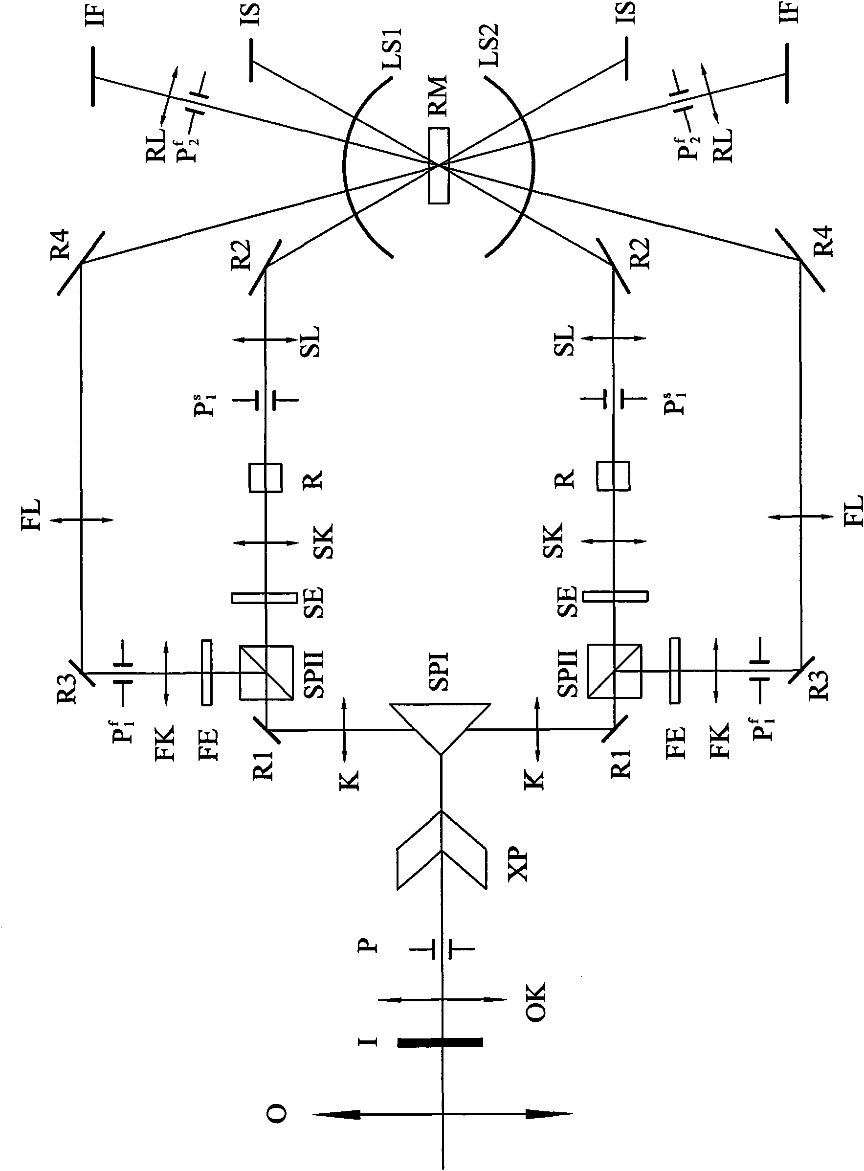
[0018] Such as figure 1 , 2 As shown, in the preferred embodiment of the planar imaging system of the optical waiting type framing scanning and simultaneous recording of the present invention, it includes an objective lens 0, a waiting beam splitting device 20 for separating two beams of primary images, and two primary images are divided into scanning The secondary spectroscopic device 30 for the light beam and the framing beam, and the framing scanning rotating mirror device 40 for imaging the scanning beam and the framing beam generated by each secondary spectroscopic device 30 on the final image plane. The object light forms a primary image after passing through the objective lens 0, and the primary image splits into two primary image beams after passing through the waiting spectroscopic device 20, which provides two incident beams for subsequent framing scanning. Each primary image beam passes through the corresponding secondary beam splitting device 30 to form two second...


PUM


Abstract

The invention relates to an optical waiting type plane imaging system for framing, scanning and simultaneous recording, comprising an objective lens, a waiting light splitter, two secondary light splitters, a framing device and a scanning device which are arranged corresponding to each secondary light splitter and a framing and scanning rotating mirror device. Two times of light splitting are realized by the waiting light splitter and the secondary light splitters, a framing optical path and a scanning optical path which are generated after light splitting both enter the framing and scanning rotating mirror device, and images are generated on a framing image plane and a scanning image plane respectively; as the framing optical path and the scanning optical path are provided with a commonobjective lens, the two paths have the same space datum and generate reflection images by the same rotating mirror, and the two paths have the same time datum, thus obtaining higher space informationand time information, high interpretation accuracy and high interpretation precision.

Description

【Technical field】 [0001] The invention relates to a framing and scanning imaging system, and more specifically relates to a plane imaging system applied to optical waiting type framing scanning and simultaneous recording in high-speed imaging technology. 【Background technique】 [0002] High-speed imaging technology is a time-magnifying technology for observing transient events, which can give space-time information of high-speed changing processes. High-speed imaging technology has experienced the development process from high-speed to very high-speed, ultra-high-speed, and extremely high-speed, from visible light to far-infrared, ultraviolet, and X-rays, from the study of the motion of macroscopic objects to the study of microscopic mechanisms. [0003] High-speed imaging technology is used in the study of emission and collision-like transient processes; the study of detonation-like ultrafast processes and high-voltage discharge-like transient processes; the study of decay ...

Claims


Application Information

Patent Timeline
IPC IPC(8): G03B39/00G02B27/10
Inventor 李景镇惠彬陆小微
Owner SHENZHEN UNIV
Learn More