
Method for assembling lugs and cover plate of battery

A technology of battery tabs and assembly method, applied in secondary batteries, battery pack components, circuits, etc., can solve problems such as affecting battery safety and cycle life, inability to precisely control welding positions, unfavorable processes, and quality control, etc. To achieve the effect of easy flow operation, reliable and firm connection point of the pole ear, and guaranteed performance

Inactive Publication Date: 2010-02-17
SHENZHEN BAK BATTERY CO LTD
View PDF1 Cites 17 Cited by
  • Summary
  • Abstract
  • Description
  • Claims
  • Application Information

AI Technical Summary

Problems solved by technology

[0003] In the current assembly process of the battery tab and the cover plate, the tab is generally welded to the pole of the cover plate. When a large current is discharged, such as when used on a hybrid electric vehicle (HEV) or a pure electric vehicle (EV), If the connection between tabs and poles is not good or the connection fails, it will cause serious heating, resulting in excessive battery temperature, and in severe cases, it will cause battery failure and affect the safety and cycle life of the battery, especially when there are multiple tabs When connecting with the pole, the welding position cannot be precisely controlled, which is not conducive to process and quality control

Method used


Image

  • Method for assembling lugs and cover plate of battery
  • Method for assembling lugs and cover plate of battery
  • Method for assembling lugs and cover plate of battery

Examples


Embodiment 1

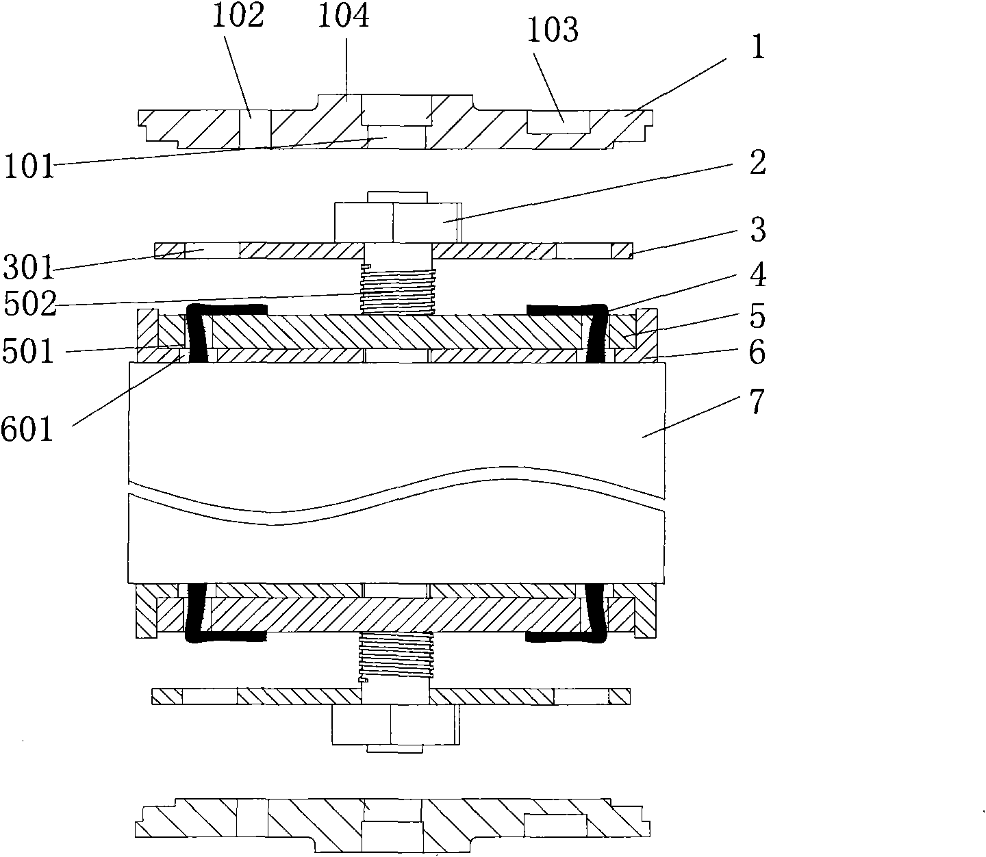
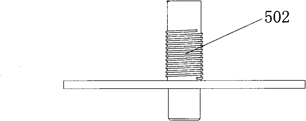
[0031] A secondary battery such as figure 1 As shown, it includes a cover plate 1 , a connector, a tab lead-out device, a second gasket 3 , and a winding core 7 . The tab lead-out device includes an insulating gasket 6 and a first gasket 5, wherein the insulating gasket 6 forms an insulating layer, and the first gasket 5 forms a conductive layer. The connecting piece includes a nut 2 and a screw 502 fixed on the first washer. The battery plate is wound into a cylindrical core 7, and there are multiple tabs 4 protruding from the core 7 at both ends. The tabs at one end are positive tabs, and the other ends are negative tabs. The connecting structure of the cover plate is the same.

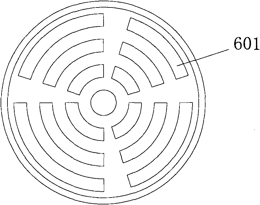
[0032] The insulating spacer 6 is circular and is placed on the end face of the winding core 7. The structure of the insulating spacer 6 is as follows: figure 2 As shown, a hole 601 is opened thereon, and the hole 601 is a discontinuous sector. A first gasket 5 is stacked above the insulating g...

Embodiment 2

[0038] A secondary battery, including a cover plate, a connector, a tab lead-out device, a second gasket, and a winding core, the difference from Example 2 is that the tab lead-out device is a composite of an insulating layer and a conductive layer Structure. Such as Figure 7 As shown, the tab lead-out device is divided into upper and lower layers, the upper layer is a conductive layer, and the lower layer is an insulating layer, and the tab passes through the hole on the tab lead-out device from below the insulating layer and is welded above the conductive layer.

Embodiment 3

[0040] A secondary battery, including a cover plate, a connector, a tab lead-out device, a second gasket, and a winding core. The difference between it and Embodiment 2 is that there is no hole on the tab lead-out device, such as Figure 8 As shown, the tab protrudes from the edge of the tab lead-out device from below the insulating layer and is welded above the conductive layer.


PUM


Abstract

The invention discloses a method for assembling lugs and a cover plate of a battery, which comprises the following steps: a) placing a lug lead-out device at the end of a battery coil core; b) electrically contacting a plurality of lugs extending out of the end of the coil core and a conductive layer of the lug lead-out device; c) compressing the lugs on the lug lead-out device through a second gasket; and d) placing the cover plate of the battery on the upper surface of the second gasket, and sealing the periphery of the cover plate of the battery and a shell of the battery. Step b) also comprises the following subsequent step: b1) bending the lugs and then welding the lugs on the conductive layer of the lug lead-out device. The lugs are welded to the lug lead-out device and mechanicallycompressed through the second gasket so as to ensure reliable connection of the lugs and posts of a battery cell, reduce the inner resistance of the battery and ensure firm fixation of the coil core.The method is simple in assembly process, is suitable for line production, is suitable for assembling the batteries of hybrid electric automobiles with multiple lugs and large volume and pure electricautomobiles and can also be used for assembling large energy-storage batteries.

Description

technical field [0001] The invention relates to the field of battery manufacturing, in particular to a method for assembling battery lugs and cover plates. Background technique [0002] A lithium-ion secondary battery consists of a negative plate, a positive plate, an electrolyte, and a separator interposed between the positive and negative plates to prevent short circuits. The positive plate and the negative plate are made into thin plates or foils, and then the electrode plates and the intervening separator are stacked in sequence or spirally wound to form a battery core, and then the battery core is filled with stainless steel, nickel-plated iron, and aluminum metal Electrolyte is poured into the casing or laminated flexible film battery container, and sealed to form a battery. Wherein, the electrical conduction between the battery core and the outside world is realized through the connection between the lug connected to the pole plate and the pole or the cover plate. ...

Claims


Application Information

Patent Timeline
IPC IPC(8): H01M2/06H01M2/20H01M10/40H01M50/152H01M50/179H01M50/559H01M50/566
CPCY02E60/12Y02E60/10
Inventor 刘道坦刘照宽黄荣光郭春泰
Owner SHENZHEN BAK BATTERY CO LTD
Learn More