
Cylinder head of internal combustion engine

A technology for internal combustion engine cylinders and cylinder heads, which is applied to cylinders, cylinder heads, mechanical equipment, etc., can solve the problems of flame propagation distance, long combustion time, high engine heat load, and low average value, etc., to reduce exhaust pollution, The effect of reducing the oil consumption of the whole machine and reducing the heat load

Inactive Publication Date: 2010-02-17
力帆科技(集团)股份有限公司
View PDF0 Cites 1 Cited by
  • Summary
  • Abstract
  • Description
  • Claims
  • Application Information

AI Technical Summary

Problems solved by technology

[0003] 1. The intake port 7 and the exhaust port 8 are distributed approximately 180° between the cavity 2 and the combustion chamber 3, which is not conducive to the formation of the vortex in the combustion chamber 3, and the residual exhaust gas at the gap between the spark plugs cannot be removed in time, which may cause combustion The mixed gas is not easy to ignite in the combustion chamber 3, resulting in insufficient combustion, resulting in high fuel consumption of the whole machine and large amount of exhaust pollution
[0004] 2. The shape of the combustion chamber 3 is elliptical, the volume is relatively large, the arrangement of intake and exhaust valve chambers and spark plugs is scattered, the distance of flame propagation and combustion time are relatively long, and the pressure rise is lower than the average value, making the engine High thermal load is not conducive to the improvement of engine power

Method used


Image

  • Cylinder head of internal combustion engine
  • Cylinder head of internal combustion engine
  • Cylinder head of internal combustion engine

Examples


Embodiment Construction

[0015] Below in conjunction with accompanying drawing and embodiment the present invention will be further described:

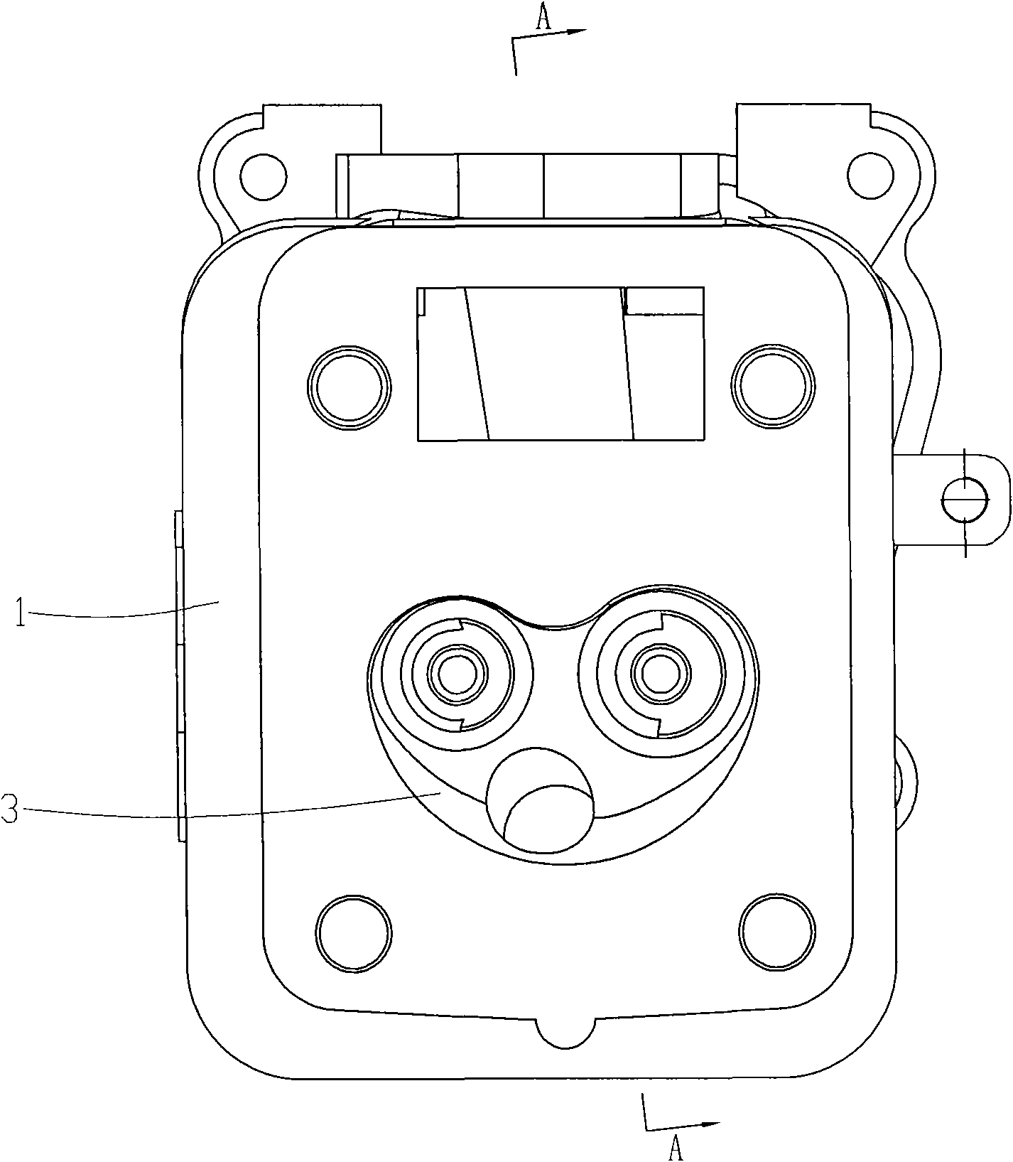
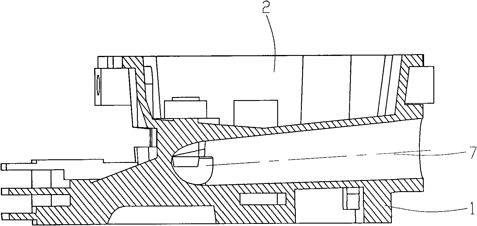
[0016] Such as figure 1 , figure 2 and image 3 As shown, the cylinder head of a general-purpose gasoline engine has a cylinder head body 1, and the cylinder head body 1 is molded by die casting, and a cavity 2, a combustion chamber 3, an intake valve chamber 4, and an exhaust valve chamber 5 are arranged on the cylinder head body 1. , valve guide 6, intake port 7 and exhaust port 8, wherein the cavity 2 is located at the top of the cylinder head body 1, and the combustion chamber 3 is located at the bottom of the cylinder head body 1, and the profile line of the combustion chamber 3 is heart-shaped, with Shorten the flame propagation distance and burning time. Two intake and exhaust valve chambers 4 and 5 arranged side by side are located between the cavity 2 and the combustion chamber 3, the bottom ends of the intake and exhaust valve chambers 4 and 5 ...


PUM

PropertyMeasurementUnit
Angleaaaaaaaaaa

Abstract

The invention discloses a cylinder head of an internal combustion engine. The body of the cylinder head is provided with a die cavity, a combustion chamber, an inlet valve chamber, an exhaust valve chamber, valve guide pipes, an inlet duct and an exhaust duct, wherein the die cavity is positioned on the top of the body of the cylinder head; the combustion chamber is positioned at the bottom of thebody of the cylinder head; the inlet valve chamber and the exhaust valve chamber arranged in parallel are positioned between the die cavity and the combustion chamber; the inlet duct is communicatedwith the combustion chamber through the inlet valve chamber; the inlet valve chamber is also communicated with the die cavity through one valve guide pipe; the exhaust duct is communicated with the combustion chamber through the exhaust valve chamber; the exhaust valve chamber is also communicated with the die cavity through another valve guide pipe; and an included angle which is between 80 and 85 degrees is formed between the central line of the inlet duct and the central line of the exhaust duct. The cylinder head of the internal combustion engine can ensure the sufficient combustion of a combustible mixed gas to effectively reduce the oil consumption of the entire engine and reduce the exhaust pollution; and simultaneously, the cylinder head of the internal combustion engine can also reduce the thermal load of the engine and improve the dynamic property of the engine, and is suitable for various types of gasoline engines.

Description

technical field [0001] The invention relates to a gasoline engine component, in particular to a cylinder head on a general-purpose gasoline engine. Background technique [0002] The structure of the gasoline engine cylinder head is as follows: Figure 4 , Figure 5 As shown, a cavity 2 is opened on the top of the cylinder head body 1, and a combustion chamber 3 with an elliptical profile is opened at the bottom of the cylinder head body 1. Two inlet and exhaust valve chambers 4 and 5 arranged side by side are located in the mold Between the cavity 2 and the combustion chamber 3, the bottom ends of the intake and exhaust valve chambers 4 and 5 communicate with the combustion chamber 3, and the top ends of the intake and exhaust valve chambers 4 and 5 communicate with the cavity 2 through the valve guide 6 respectively. The left and right sides between the cavity 2 and the combustion chamber 3 are also respectively provided with an intake passage 7 and an exhaust passage 8, w...

Claims


Application Information

Patent Timeline
IPC IPC(8): F02F1/42
Inventor 王中梅任健
Owner 力帆科技(集团)股份有限公司
Learn More