Liquid crystal display panel with microlens array and method for manufacturing the same

一种液晶显示面板、微透镜阵列的技术,应用在透镜、仪器、光学等方向,能够解决液晶显示面板100显示品质降低等问题,达到抑制冲击或者压力的效果

Inactive Publication Date: 2011-04-13
SHARP KK
View PDF4 Cites 1 Cited by
  • Summary
  • Abstract
  • Description
  • Claims
  • Application Information

AI Technical Summary

Problems solved by technology

However, in this manufacturing process, when the unnecessary part of the dry film is removed by development in the process of forming the protective layer 135, the developer and the uncured dry film enter the internal space through the vent hole 127, thereby causing the liquid crystal display panel to be damaged. 100 display quality reduction issues

Method used


Image

  • Liquid crystal display panel with microlens array and method for manufacturing the same
  • Liquid crystal display panel with microlens array and method for manufacturing the same
  • Liquid crystal display panel with microlens array and method for manufacturing the same

Examples


Embodiment Construction

[0117] Hereinafter, embodiments of the liquid crystal display panel of the present invention will be described with reference to the drawings.

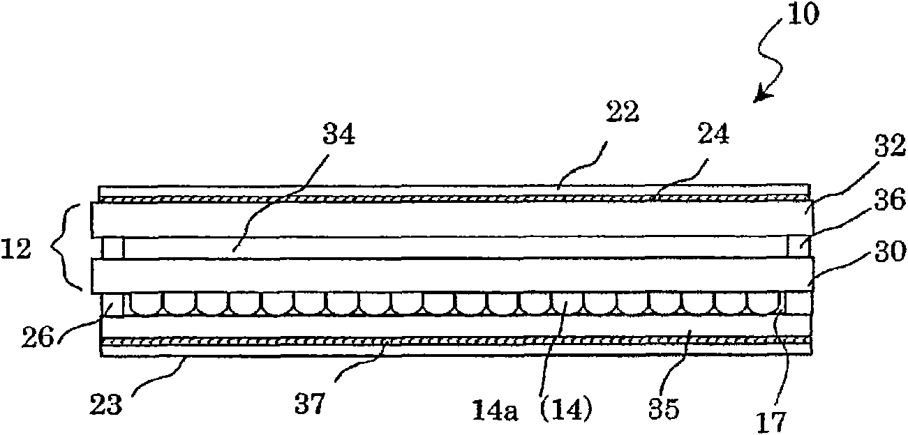
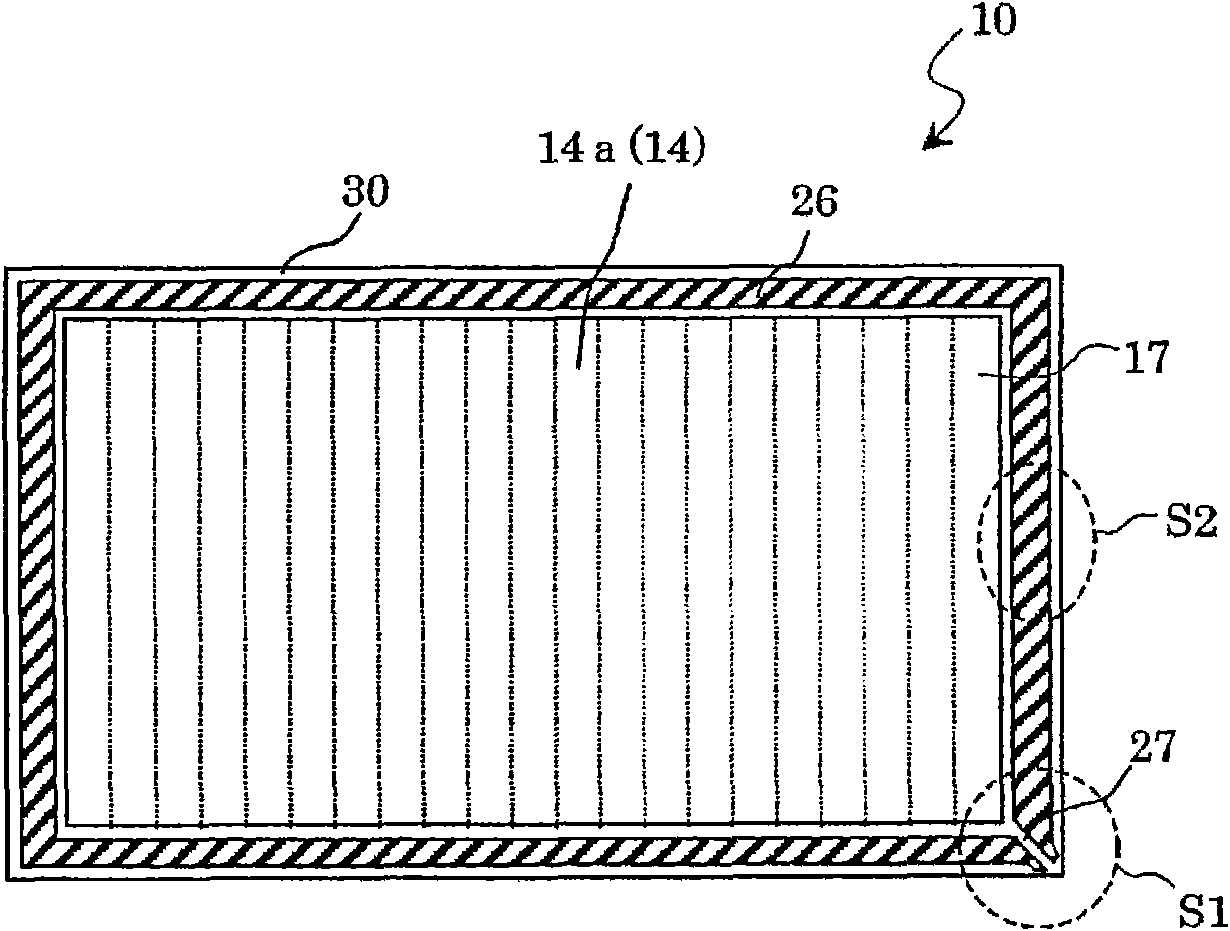
[0118] figure 1 is a cross-sectional view of the liquid crystal display panel 10 of this embodiment, figure 2 is the light incident side from the backlight ( figure 1 The lower side of the liquid crystal display panel 10 is a diagram showing the structures of the microlens array, the support, and the like.

[0119] like figure 1 and figure 2 As shown, the liquid crystal display panel 10 includes: a bonded substrate 12; a microlens array 14 composed of a plurality of microlenses 14a arranged on the backlight light incident side of the bonded substrate 12; a support set around the microlens array 14 body 26; on the viewer side of the bonded substrate 12 ( figure 1 and the protective layer 35 and the optical film 23 provided on the light incident side of the backlight of the microlens array 14 . When viewed from a direction p...


PUM


Abstract

A highly reliable liquid crystal display panel in which such a trouble as mixture of foreign material is prevented. The reliable liquid crystal display panel comprises a bonded substrate including a pair of substrates and a liquid crystal layer arranged therebetween, a microlens array provided on the light incident side of the bonded substrate, a support provided on the light incident side of thebonded substrate to surround the microlens array, and an optical film attached to the bonded substrate through the support. The support has a portion projecting farther to the outer space side than the major surface of the outer surface of the support, and a vent connecting the inner space surrounded by the support and the outer space. The opening of the vent on the outer space side is formed in the projection.

Description

technical field [0001] The present invention relates to a liquid crystal display panel, in particular to a liquid crystal display panel and a liquid crystal display device provided with a microlens array. Background technique [0002] In recent years, liquid crystal display devices have been widely used as display devices such as monitors, projectors, portable information terminals, and mobile phones. In a liquid crystal display device, generally, the transmittance (or reflectance) of the liquid crystal display panel is changed by a driving signal, and the intensity of light from a light source irradiated on the liquid crystal display panel is modulated to display images and characters. Among liquid crystal display devices, there are direct-view display devices that directly observe images displayed on a liquid crystal display panel, and projection display devices (projectors) that enlarge and project images displayed on a display panel on a screen using a projection lens. ...

Claims


Application Information

Patent Timeline
Patent Type & Authority Patents(China)
IPC IPC(8): G02F1/1335G02B3/00G02F1/1333
CPCG02F2001/133567G02B3/005G02F1/133351G02F1/133526G02F1/133567
Inventor 柴田谕佐佐木伸夫村尾岳洋吉水敏幸
Owner SHARP KK
Why Eureka
Try Eureka