Permanent magnet rotary electric machine and permanent magnet motor drive system
一种永久磁铁、驱动系统的技术,应用在带有静止电枢和旋转磁体的同步电动机、电子换向电动机控制、电动机控制等方向,能够解决无法得到充分的输出、综合运转效率恶化、电动机损失等问题,达到材料削减、制造性提高、可靠性提高的效果
- Summary
- Abstract
- Description
- Claims
- Application Information
AI Technical Summary
Problems solved by technology
Method used
Image

Examples
no. 1 approach
[0049] (Permanent magnet type rotating electrical machine)
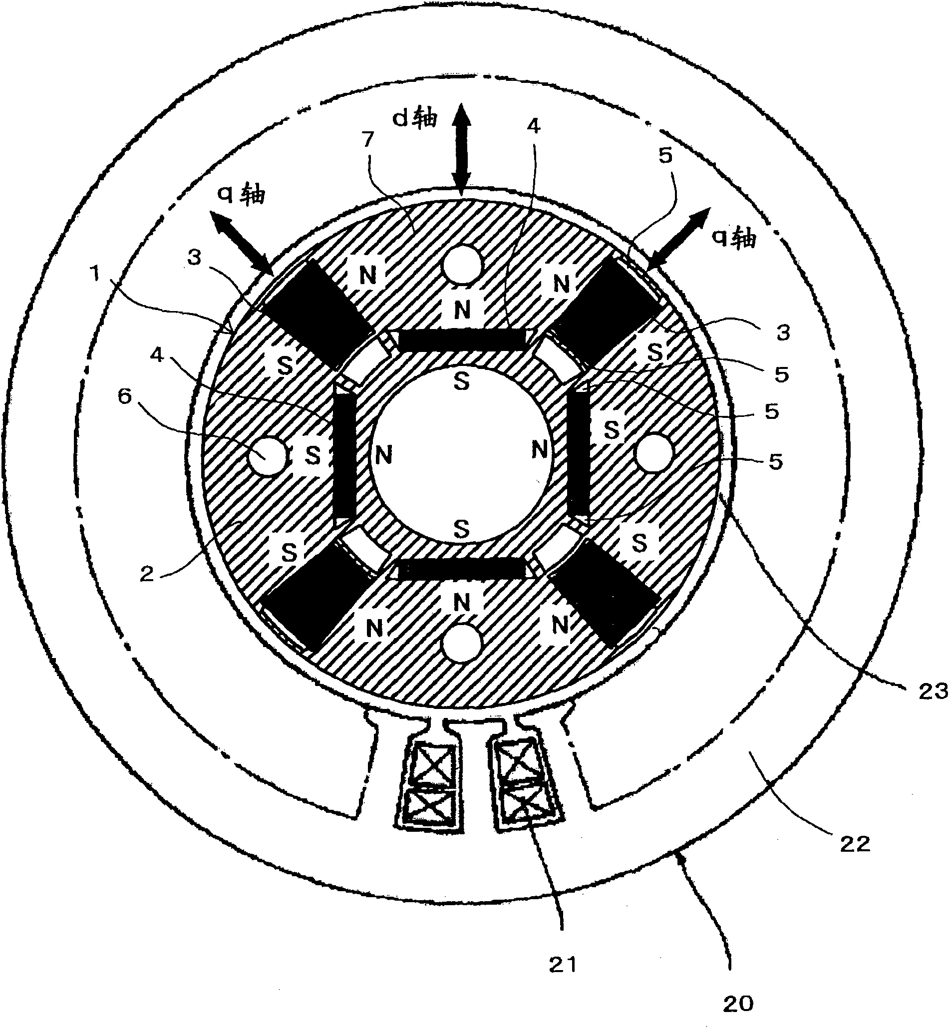
[0050] use Figure 1 to Figure 6 , the permanent magnet type rotating electric machine according to the first embodiment of the present invention will be described. figure 1 The configuration of the permanent magnet type rotating electrical machine according to the present embodiment is shown, and the rotor 1 is accommodated in the stator 20 so as to face each other with the air gap 23 interposed therebetween. In addition, the stator 20 is the same as the conventional example, and Figure 20 same.
[0051] Such as figure 1 As shown, the rotor 1 in the permanent magnet type rotating electrical machine of this embodiment includes a rotor core 2, a permanent magnet 3 with a small product of the coercive force and the thickness in the magnetization direction, and a permanent magnet 4 with a large product of the coercive force and the thickness in the magnetization direction . The rotor core 2 is composed of laminat...
no. 2 approach
[0130] A permanent magnet type rotating electrical machine and a permanent magnet motor drive system according to a second embodiment of the present invention will be described. The present embodiment is characterized in that, relatively figure 1 The permanent magnet rotating electrical machine 101 shown utilizes Figure 7 In the permanent magnet motor drive system shown, the alnico permanent magnet 3 is irreversibly magnetized by a pulsed magnetic field generated by a short-term d-axis current to change the linkage flux.
[0131] In this way, in the medium-speed rotation domain and the high-speed rotation domain, the magnetic flux is always generated by the negative d-axis current, so that the magnetic flux generated by the above-mentioned negative d-axis current can be adjusted, including the magnetic flux generated by the negative d-axis current. The interlinkage flux of the magnetic flux and the magnetic flux generated by the permanent magnets 3 and 4. That is, in the m...
no. 3 approach
[0134] use Figure 13 , a permanent magnet type rotating electrical machine according to a third embodiment of the present invention will be described. The structure of the stator 20 in the permanent magnet type rotating electrical machine of the present embodiment and figure 1 Part of the first embodiment shown, Figure 20 The part of the conventional example shown is the same.
[0135] Such as Figure 13 As shown, in the rotor 1 of the present embodiment, the AlNiCo permanent magnets 3 are arranged radially in the rotor core 2 on the q-axis, and the NdFeB permanent magnets 4 are perpendicular to the d-axis so as to be in contact with each other in the circumferential direction. Arranged in the rotating core 2. The rotor 1 is configured such that an iron shaft 9 is fitted into an inner peripheral side of a rotor core 2 . The shaft 9 has a four-sided shape, and an air layer 8 is formed between the rotor core 2 and the shaft 9 . In addition, the shaft 9 may be made of a n...
PUM
 Abstract
Description
Claims
Application Information
 - Generate Ideas
- Intellectual Property
- Life Sciences
- Materials
- Tech Scout
- Unparalleled Data Quality
- Higher Quality Content
- 60% Fewer Hallucinations
Browse by: Latest US Patents, China's latest patents, Technical Efficacy Thesaurus, Application Domain, Technology Topic, Popular Technical Reports.
© 2025 PatSnap. All rights reserved.Legal|Privacy policy|Modern Slavery Act Transparency Statement|Sitemap|About US| Contact US: help@patsnap.com