Roller cam direct drive transmission mechanism
A technology of roller cam and transmission mechanism, which is applied in transmission devices, mechanical equipment, belts/chains/gears, etc. It can solve problems such as heavy weight of shells and mechanisms, difficulty in manufacturing large-scale mechanisms, and complex power input and output, etc. The effect of simplified structure, simple structure and high economic value
- Summary
- Abstract
- Description
- Claims
- Application Information
AI Technical Summary
Problems solved by technology
Method used
Image

Examples
Embodiment 1
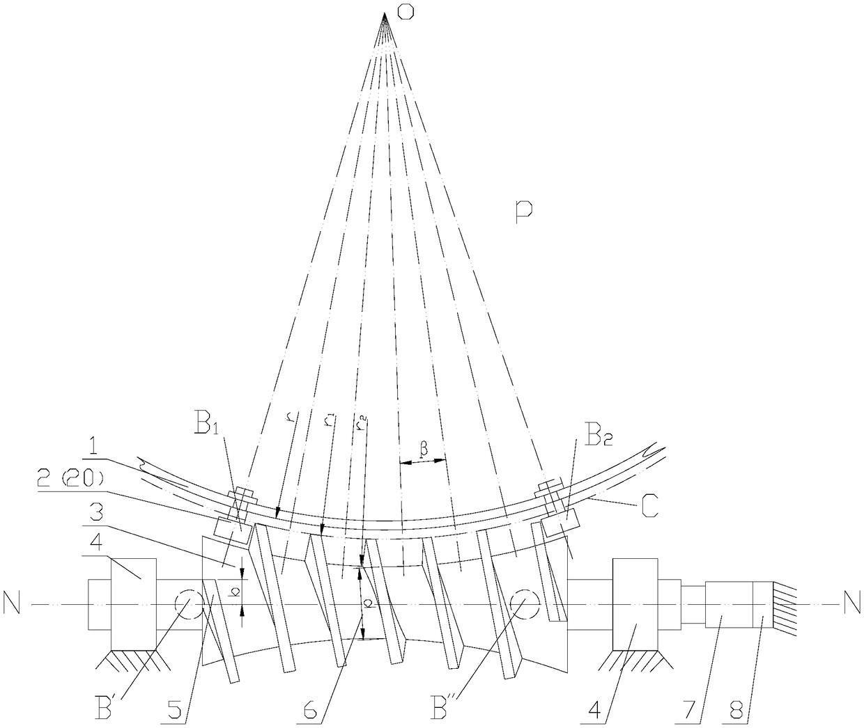
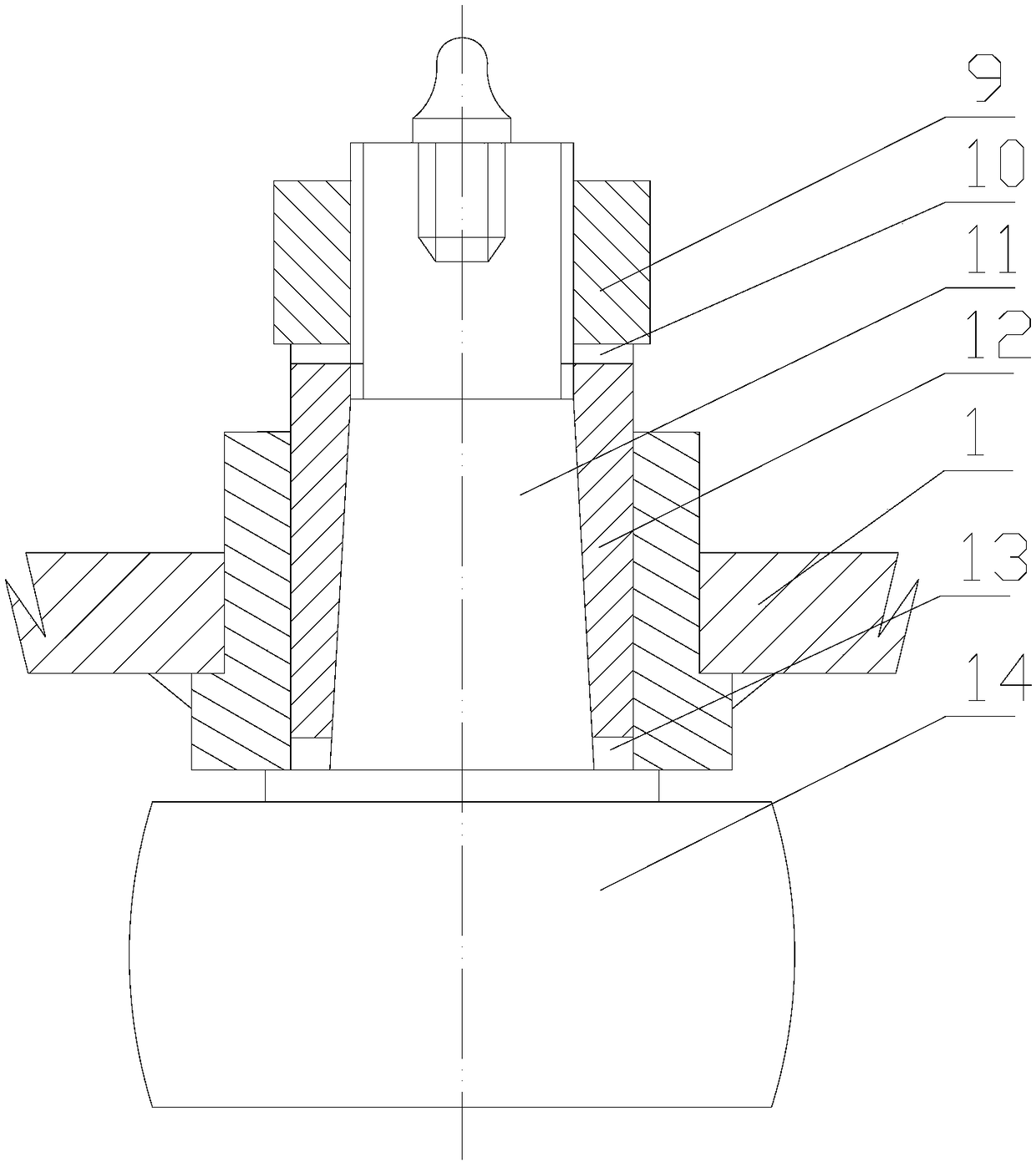
[0048] Such as figure 1 , 2 As shown, the present invention provides a roller cam direct drive transmission mechanism, which includes: a revolving body 1, a roller A2, and a cam 3; the roller A2 is mounted on the revolving body 1; it is characterized in that:
[0049] The revolving body 1 is a component that needs to be driven directly or indirectly in a certain device. On the vertical plane P of the revolving body axis, with P and the focal point O of the axis as the center, along the meridian that divides the angle by the transmission ratio around the revolving body Set the mounting hole 13 of the roller;
[0050] Roller A2 is a roller bearing assembly with a bolt shaft; Roller A2 includes: roller 14 and bolt shaft A11; Bolt shaft A11 is a tapered shaft; Roller A2 is fixedly installed around the revolving body 1 through mounting assembly A In the hole 13, a roller revolving body is formed;
[0051] The cam 3 is a curved cylindrical grooved space structure; the assembly position, s...
Embodiment 2
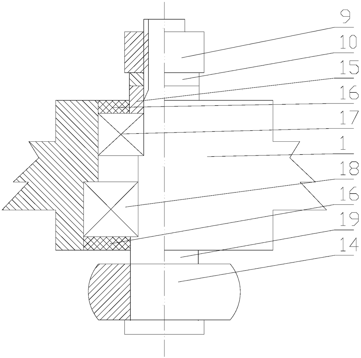
[0062] Such as figure 1 , 3 As shown, the present invention provides a roller cam direct drive transmission mechanism, which includes: a revolving body 1, a roller B20, and a cam 3; the roller B20 is mounted on the revolving body 1; it is characterized in that:
[0063] The revolving body 1 is a component that needs to be driven directly or indirectly in a certain device. On the vertical plane P of the revolving body axis, with P and the focal point O of the axis as the center, along the meridian that divides the angle by the transmission ratio around the revolving body Set the mounting hole 13 of the roller;
[0064] Roller B20 is a roller bearing assembly with a bolt shaft; Roller B20 includes: Roller 14 and bolt shaft B19; Bolt shaft B19 is a cylindrical shaft; Roller B20 is fixedly installed around the rotating body 1 through mounting assembly B In the hole 13, or directly installed in the mounting hole 13 around the revolving body 1 through the bolt shaft B19, a roller revolvi...
specific Embodiment 3
[0075] For a device with a transmission ratio of 60 and a torque of 50KN, try to make a brief design process of a roller cam direct drive transmission mechanism.
[0076] Such as figure 1 Shown is the schematic diagram of the roller cam direct drive transmission mechanism. The brief design process is:
[0077] According to the mechanical strength required for a torque of 50KN, the roller model is φ100×60, the outer diameter is 100mm, the width is 60mm, the wall thickness between the cam grooves is 25mm, and the spiral groove lead arc length is 125mm.
[0078] The radius of the pitch line of the roller and groove = (125x60) / 2π = 1194
[0079] The arc C is the outer arc surface of the cam 3 and also the radius r of the outer end surface of the roller mounting seat hole on the rotating body 1. 1 , R 1 =1194-60 / 2=1164
[0080] On the revolving body 1 with a radius of r, a plane P perpendicular to the axis is set, and the point of intersection with the axis is the center of the revolving bod...
PUM
| Property | Measurement | Unit |
|---|---|---|
| Outer diameter | aaaaa | aaaaa |
| Width | aaaaa | aaaaa |
Abstract
Description
Claims
Application Information
 - Generate Ideas
- Intellectual Property
- Life Sciences
- Materials
- Tech Scout
- Unparalleled Data Quality
- Higher Quality Content
- 60% Fewer Hallucinations
Browse by: Latest US Patents, China's latest patents, Technical Efficacy Thesaurus, Application Domain, Technology Topic, Popular Technical Reports.
© 2025 PatSnap. All rights reserved.Legal|Privacy policy|Modern Slavery Act Transparency Statement|Sitemap|About US| Contact US: help@patsnap.com