Method, system and equipment for detecting path loss

A technology of path loss and path measurement, applied in transmission systems, transmission monitoring, electrical components, etc., can solve the problems that the system cannot control uplink interference, the system cannot effectively schedule resources, etc., to achieve easy control, easy implementation, and optimization of the system. performance effect

Active Publication Date: 2012-10-10
DATANG MOBILE COMM EQUIP CO LTD
View PDF0 Cites 0 Cited by
  • Summary
  • Abstract
  • Description
  • Claims
  • Application Information

AI Technical Summary

Problems solved by technology

[0007] The purpose of the present invention is to propose a method, system and equipment for measuring path loss, so that the terminal can accurately measure the path loss of adjacent cells with the same frequency, so as to overcome the inability of the system to accurately understand when the terminal reports the scheduling request information SI in the prior art One or more problems such as the communication environment of the current terminal, the inability of the system to effectively perform resource scheduling, and the inability of the system to control uplink interference

Method used


Image

  • Method, system and equipment for detecting path loss
  • Method, system and equipment for detecting path loss
  • Method, system and equipment for detecting path loss

Examples


Embodiment Construction

[0035] Specific embodiments of the invention will now be described in detail, examples of which are illustrated in the accompanying drawings. The present invention is described below by referring to the accompanying drawings, which are only for explaining the present invention and cannot be construed as limiting the present invention.

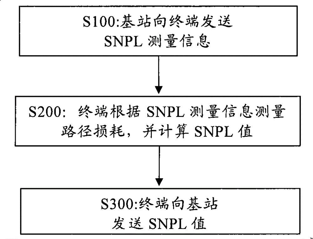
[0036] The invention discloses a method for measuring path loss, comprising the following steps:

[0037] The base station sends the SNPL measurement information of the path loss of the adjacent cell to the terminal; the terminal measures the path loss of the adjacent cell with the same frequency as the operating frequency of the terminal according to the SNPL measurement information, and calculates the SNPL value; The SNPL value is sent to the base station.

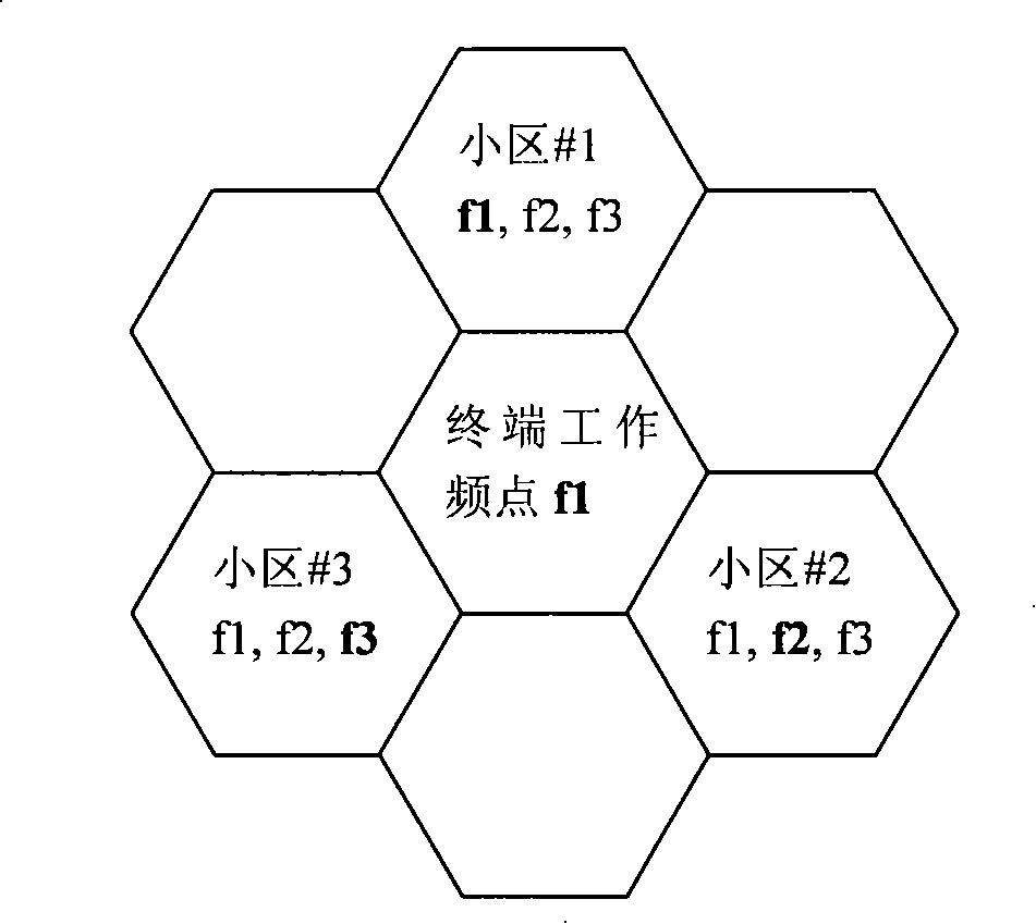
[0038] In each embodiment of the present invention, the working frequency of the terminal refers to the frequency used by the terminal for uplink.

[0039] Such as figure 1 As shown, i...


PUM


Abstract

The invention discloses a method for detecting path loss. The method comprises the following steps that: a base station sends SNPL detection information on the path loss of a neighbor cell; a terminal detects the pass loss of the adjacent cell having the same frequency as the terminal according to the SNPL detection information, and works out an SNPL value; and the terminal sends the SNPL value to the base station. The invention also discloses a system and the equipment for detecting the path loss. According to the technical scheme provided by the invention, the terminal can accurately detectthe path loss the neighbor cells with the same frequency, the system can accurately understand the communication environment of the current terminal, the resource allocation of the system can be conveniently made, and simultaneously the uplink interference control by the system can also be made convenient.

Description

technical field [0001] The present invention relates to the field of mobile communication, in particular to a method, system and equipment for measuring path loss. Background technique [0002] With the development of mobile communication, users have higher and higher requirements on the performance of mobile communication. At present, in the third generation mobile communication system, the downlink communication capability has been greatly improved. In order to improve the uplink access capability, the 3rd Generation Mobile Communication Standardization Partnership Project (3GPP, 3rd Generation Partnership Project) organization has successively implemented Frequency Division Duplex (FDD, Frequency Division Duplex) in Release 6 (Release 6) and Release 7 (Release 7). Time Division Duplex (TDD, Time Division Duplex) introduces Enhanced Uplink (Enhanced Uplink) technology, also known as High Speed ​​Uplink Packet Access (HSUPA, High Speed ​​Uplink Packet Access), which aims t...

Claims


Application Information

Patent Timeline
Patent Type & Authority Patents(China)
IPC IPC(8): H04W24/00H04B17/00
CPCH04W24/08
Inventor 朱向前李晓卡全海洋
Owner DATANG MOBILE COMM EQUIP CO LTD
Why Eureka
Try Eureka