Liquid crystal display
A liquid crystal display, technology of liquid crystal molecules, used in static indicators, instruments, nonlinear optics, etc.
- Summary
- Abstract
- Description
- Claims
- Application Information
AI Technical Summary
Problems solved by technology
Method used
Image
Examples
Embodiment 1
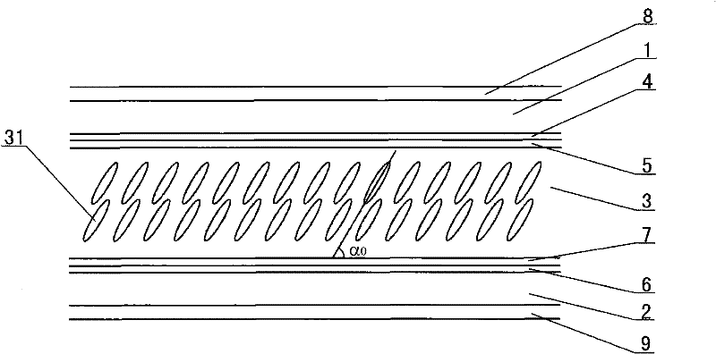
[0038] This liquid crystal display can be driven actively or passively. The display area of the liquid crystal display includes several pixels or segments, which are the smallest unit for controlling light in the liquid crystal display, and the area in the pixels or segments that can control the on-off of light on the plane of the liquid crystal display is called the active area. The section of the active area has the above-mentioned upper polarizer 8, upper transparent substrate 1, upper electrode 4, upper alignment layer 5, negative liquid crystal layer 3, lower alignment layer 7, lower electrode 6, lower transparent substrate 2 and The layered structure formed by the lower polarizer 9.
[0039] Both the upper electrode 4 and the lower electrode 6 are thin films made of a light-transmitting conductive material (such as ITO), and are respectively attached to the inner surfaces of the upper transparent substrate 1 and the lower transparent substrate 2 .
[0040] The upper p...
Embodiment 2
[0051] Example 3
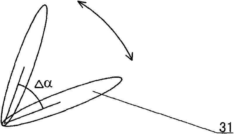
[0052] This embodiment is further improved on the basis of the liquid crystal display of embodiment 1, 2, and the liquid crystal display adopts the following drive mode (this drive mode is called the jitter drive mode, refer to image 3 ): by controlling the periodic change of the driving signal, the inclination angle of the liquid crystal molecules 31 in the negative liquid crystal layer 3 is periodically changed within a certain range (ie Δα), that is, the liquid crystal molecules 31 are within a certain angle range (ie Δα ) oscillates periodically.
Embodiment 3
[0054] Assuming that the tilt angle of the liquid crystal molecules 31 is at α 1 、α 2 between changes (that is, liquid crystal molecules 31 at a tilt angle of α 1 、α 2 oscillating constantly), and there is α 1 >α 2 , swing amplitude Δα=α 1 -α 2 , then the characteristics of the driving signal waveform of the jitter drive are: periodic waveform, each cycle (called the jitter cycle) contains T 1 , T 2 Two paragraphs, where T 1 The effective value of the driving voltage of the segment is V eff1 ,T 2 The effective value of the driving voltage of the segment is V eff2 , with V eff2 eff1 , V eff2 The optimal value can be taken as zero; T 1 for the V eff1 Under the action of liquid crystal molecules 31 by α 1 change inverted alpha 2 time, T 2 for the V eff2 Under the action of liquid crystal molecules 31 by α 2 revert to alpha 1 time. So T 1 , T 2 By the coefficients of elasticity and viscosity of the negative liquid crystal layer 3, and the voltage V eff1 , T...
PUM
| Property | Measurement | Unit |
|---|---|---|
| angle | aaaaa | aaaaa |
| angle | aaaaa | aaaaa |
Abstract
Description
Claims
Application Information
 - Generate Ideas
- Intellectual Property
- Life Sciences
- Materials
- Tech Scout
- Unparalleled Data Quality
- Higher Quality Content
- 60% Fewer Hallucinations
Browse by: Latest US Patents, China's latest patents, Technical Efficacy Thesaurus, Application Domain, Technology Topic, Popular Technical Reports.
© 2025 PatSnap. All rights reserved.Legal|Privacy policy|Modern Slavery Act Transparency Statement|Sitemap|About US| Contact US: help@patsnap.com


