
Upward forming method of thermal dip-coating copper covered steel and upward forming device thereof

A forming method and technology of copper-clad steel, applied in the production of copper-clad steel by hot dip coating, and the field of copper-clad steel production, which can solve the problems of disorderly vibration, accelerated inlet and outlet contact wear, long soaking time of steel core rods, etc.

Inactive Publication Date: 2010-01-20
曹佩荣
View PDF0 Cites 13 Cited by
  • Summary
  • Abstract
  • Description
  • Claims
  • Application Information

AI Technical Summary

Problems solved by technology

[0005] (2) Due to the weight of the copper-clad steel rod and lying on the entrance and exit of the wire, when the wire is pulled at high speed, the steel core rod and the copper-clad steel rod will vibrate in disorder, which will cause the cast structure that is gradually solidified and combined to be asymmetrical ( Eccentricity), but also accelerates the wear of the inlet and outlet, and increases the out-of-roundness of the copper-clad steel rod
[0006] (3) Since the steel core rod is soaked in copper water for too long, the surface temperature of the steel core passing through the high-temperature copper water will be greater than 760 ° C, and some phosphorus ions will dissociate into the copper water and pollute the copper water, resulting in a sharp drop in conductivity. Destroy the electrical properties of copper-clad steel

Method used


Image

  • Upward forming method of thermal dip-coating copper covered steel and upward forming device thereof
  • Upward forming method of thermal dip-coating copper covered steel and upward forming device thereof
  • Upward forming method of thermal dip-coating copper covered steel and upward forming device thereof

Examples


Embodiment Construction

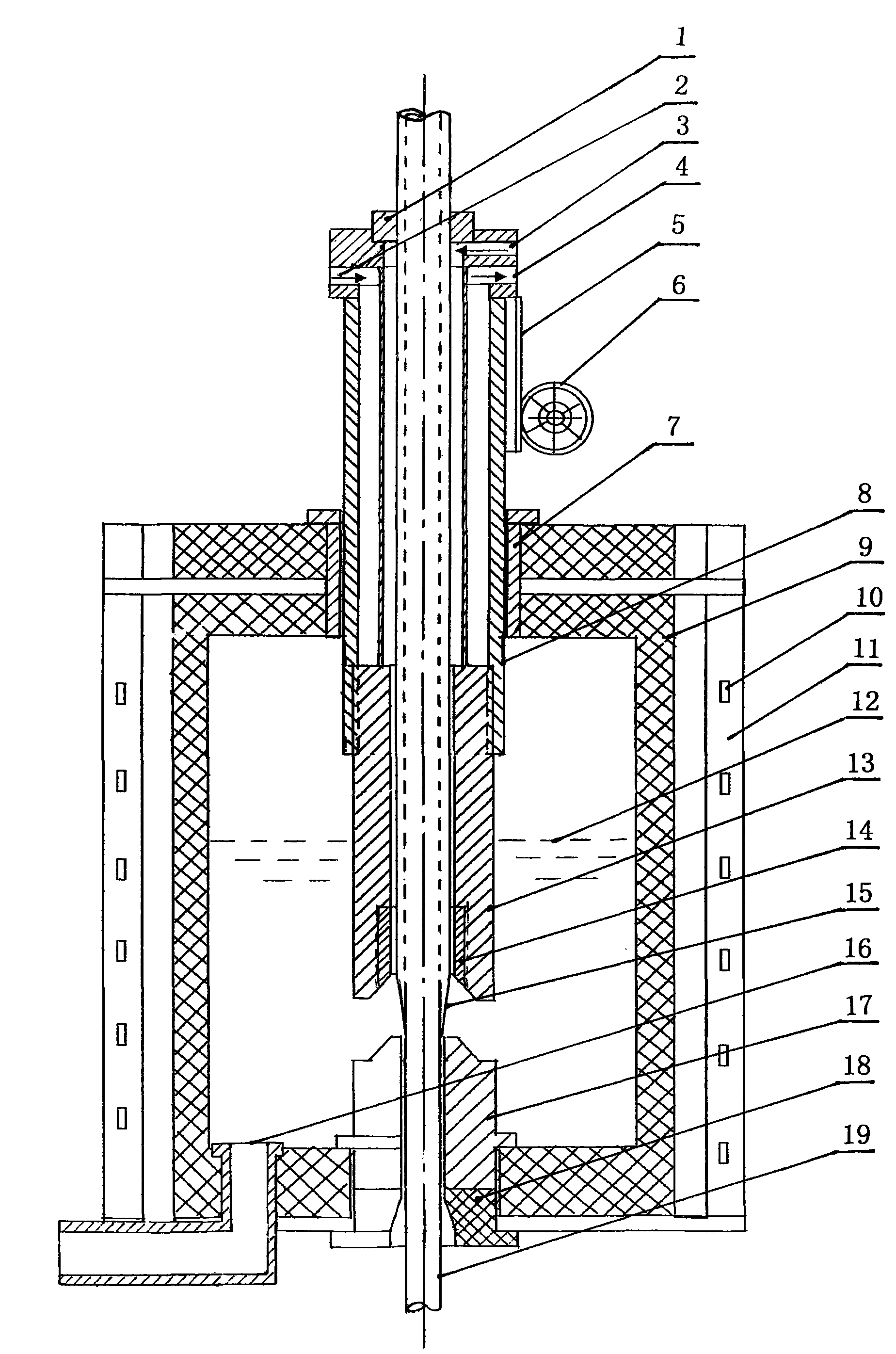
[0017] The hot-dip coated copper-clad steel upward forming method of the present invention, the key is to enter the preheated steel rod from the bottom of the crucible, and then dip-coat it from the copper water in the crucible and then pull it out vertically from the top of the crucible. The specific control method of other parameters is further described in detail as follows:

[0018] 1. The preheating temperature of the steel rod is inversely proportional to the electrical conductivity. The corresponding preheating temperature of 21-70% IACS is 500-60°C. It is not possible to obtain a CS wire with a copper coating ratio of 20% (about 30% IACS). Only by heating the steel wire to increase its temperature and reduce the amount of heat exchange per unit time can the amount of copper coating be reduced. In this way, a CS line with a low covering ratio can be obtained. If the wire is dip-coated for the second time, a CS wire with a copper-clad steel cladding ratio of 80% can be ...


PUM


Abstract

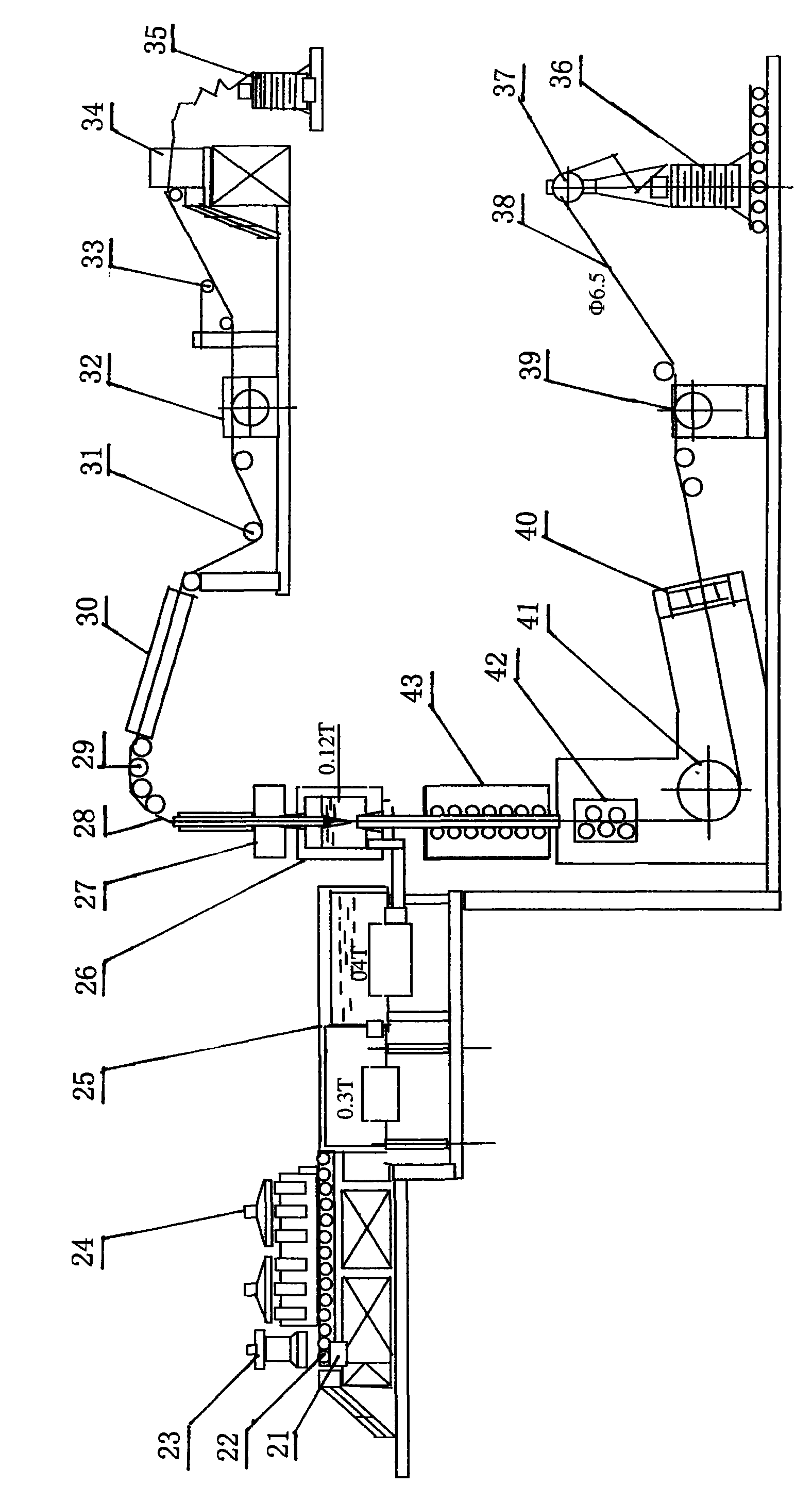
The invention relates to an upward forming method of thermal dip-coating copper covered steel. The upward forming method mainly comprises the following steps: enabling a preheated steel bar to enter the bottom of a crucible; sequentially dipping and coating the preheated steel bar in copper water of the crucible; and vertically pulling out the preheated steel bar from the upper part of the crucible. An upward forming device corresponding to the method comprises a copper water pretreatment device, a steel bar pretreatment device, the crucible, a winding device, a graphite tube, an upper graphite tube, a cooling tube, a lifting tube and a lifting device. The method mainly changes the prior horizontal forming into vertical upward forming to equalize the surface periphery temperature and the surface heat absorption capacity of the steel bar, thoroughly solves the problem of eccentric copper coating, controls the preheating temperature, the copper water temperature, the dip-coating distance and the dip-coating speed of the steel bar in suitable ranges, not only enables a copper-steel interface to have enough bonding strength, but also effectively prevents phosphonium ions in the steel bar from entering to pollute the copper water, enables the copper covered steel product to have the advantages of high strength, high conductivity, low cost, and the like and is most suitable for being used as overhead conductors and lightning conductors of a power network.

Description

technical field [0001] The invention relates to a method and equipment for producing copper-clad steel, in particular to a method and equipment for producing copper-clad steel by using hot-dip coating, belonging to the field of plating copper water dipped on a steel rod substrate. Background technique [0002] Copper clad steel wire is abbreviated as CCS. It is a double metal wire coated with copper on the surface of the steel core wire; generally the coating ratio of the copper layer is 20% to 30%, and the electrical conductivity is 21 to 40% IACS. The main production methods are: casting hot pressing method, electroplating method, copper strip crimping method, hot dip coating method, welded pipe coating method, and casing coating method. Although these methods can produce copper-clad steel, they have obvious disadvantages. For example, the casting hot-pressing method (casting-rolling method) has a long process flow, and the material utilization rate is low, and the quali...

Claims


Application Information

Patent Timeline
Patent Type & Authority Applications(China)
IPC IPC(8): C23C2/38C23C2/04B22D19/16B22D19/08B22D11/14
Inventor 曹佩荣
Owner 曹佩荣
Learn More