Eureka AIR delivers breakthrough ideas for toughest innovation challenges, trusted by R&D personnel around the world.

Clearing device for smoke pollutants of glass kiln and clearing method thereof

A technology for glass furnaces and pollutants, applied in glass furnace equipment, combined devices, separation methods, etc., can solve problems such as large water consumption, low efficiency, and easy corrosion of equipment, and achieve low dust load on filter bags and stable system operation , the effect of small footprint

Inactive Publication Date: 2010-01-20
FUJIAN LONGKING DSDN ENGINEERING CO LTD
View PDF1 Cites 33 Cited by
  • Summary
  • Abstract
  • Description
  • Claims
  • Application Information

AI Technical Summary

Problems solved by technology

Wet desulfurization has high efficiency, but it has disadvantages such as large water consumption, secondary pollution of discharged wastewater, and high investment and operating costs; dry desulfurization has low efficiency, but it can meet environmental protection requirements and can handle various pollutants. It has the advantages of low investment and operation costs
[0004] For the flue gas treatment of glass kilns with small flue gas volume, due to the high flue gas temperature, small flue gas volume, and the limitation of site, investment and operation costs and other factors, simple wet flue gas treatment technology is mostly used at present. , the system is simple and the investment cost is low, but the operation is unstable, the equipment is easy to corrode, and it can only treat a single pollutant (SO 2 ) and other shortcomings, it is difficult to meet strict environmental protection requirements

Method used


Image

  • Clearing device for smoke pollutants of glass kiln and clearing method thereof

Examples


Embodiment Construction

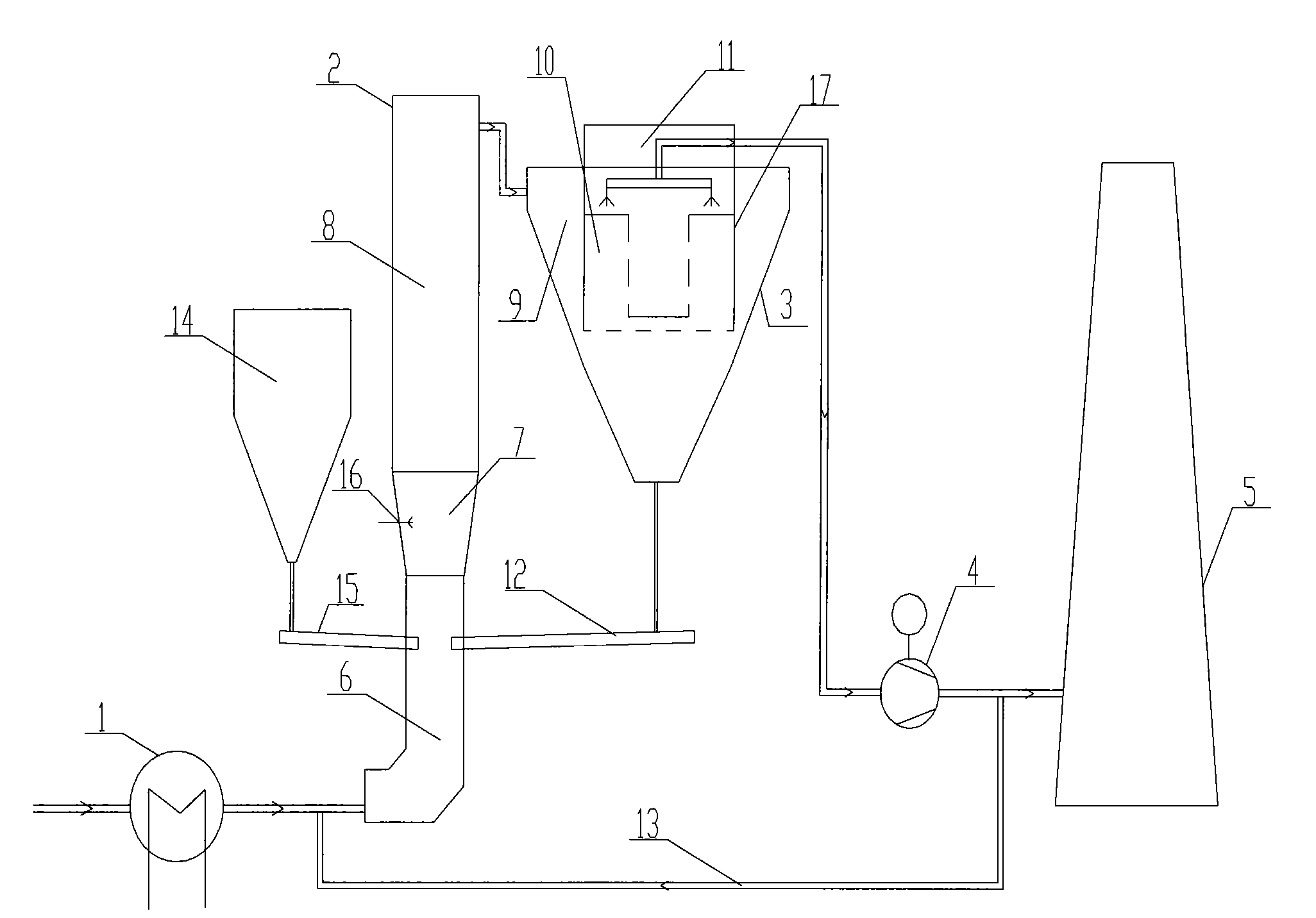
[0024] like figure 1 As shown, the glass kiln flue gas pollutant removal device of the present invention is provided with a waste heat recovery boiler 1, a reaction tower 2, a swirl type multi-stage combined bag filter 3, a circulating fluidization chute 12, a cleaning Flue gas recirculation flue 13 , absorbent bin 14 , feed air chute 15 , induced draft fan 4 and chimney 5 . Among them, the reaction tower 2 is equipped with a high-temperature reaction zone 6, a Venturi acceleration zone 7 and a circulating fluidized reaction zone 8, and the high-temperature reaction zone 6 is set at the bottom of the reaction tower 2, and the flue gas inlet of the high-temperature reaction zone 6 is externally connected to a glass furnace through a flue The exhaust port of the waste heat boiler, the circulating fluidized reaction zone 8 is set on the upper part of the reaction tower 2 , and the Venturi acceleration zone 7 is set between the high temperature reaction zone 6 and the circulating ...


PUM


Abstract

The invention relates to smoke treatment, in particular provides a clearing device for smoke pollutants of a glass kiln and a clearing method thereof. The clearing device is suitable for the glass kiln with high smoke temperature, smaller smoke amount, high clearing efficiency, stable system operation, simple structure and small floor area and is provided with an afterheat recovery boiler, a reaction tower, a bag dust collector, a circulating fluidization flume, a clean smoke recirculating flue, an absorbent bin and a feeding air flume which are sequentially connected. The clearing method comprises the following steps: smoke emitted by the glass kiln enters the afterheat recovery boiler; original smoke emitted by the afterheat recovery boiler enters a high-temperature reaction region of the reaction tower for premixing treatment with an absorbent, is accelerated by a Venturi accelerating region before entering a circulating fluidization reaction region and is cooled and purified before entering the bag dust collector; the purified smoke emitted from the reaction tower firstly enters the bag dust collector to remove particles and is emitted to a chimney by a draft fan in a purification chamber; and reaction dust emitted by the reaction tower is collected by the bag dust collector and is returned to the high-temperature reaction region.

Description

technical field [0001] The invention relates to a flue gas treatment, in particular to a dry removal device and a removal method for various pollutants in the flue gas of a glass kiln. Background technique [0002] In the production process of glass kilns, a large amount of energy is consumed, and the pollutants produced by fuel combustion include extremely harmful acid gases (SO 2 , SO 3 , HF, HCl, etc.), heavy metals (Hg, etc.) and dust, etc. Among them, the acid gas not only pollutes the environment, destroys the ecology, directly endangers the health of the human body, but also directly affects the production quality of the product and corrodes the production equipment. [0003] At present, large-scale treatment and control have been carried out on the flue gas of coal-fired boilers and steel sintering machines of large-scale power generation and heating units. The flue gas treatment technologies used can be mainly divided into two categories: wet method and dry method...

Claims


Application Information

Patent Timeline
Patent Type & Authority Applications(China)
IPC IPC(8): B01D53/83B01D53/50B01D53/68B01D53/64B01D50/00C03B5/16F27D17/00
Inventor 陈宗华张原赖毅强郑进朗张志文陈燕玲卢茂源
Owner FUJIAN LONGKING DSDN ENGINEERING CO LTD
Why Eureka
Eureka Blog
Learn More