Thin film solar cell component and encapsulation method thereof

A solar cell and packaging method technology, which is applied to electrical components, circuits, semiconductor devices, etc., can solve the problems of shortening the service life of components, poor moisture resistance, and easy corrosion of components, and achieves improved impact resistance and good resistance. The effect of mechanical damage ability and good adaptability to the environment

Inactive Publication Date: 2010-01-06
GS SOLAR FU JIAN COMPANY
View PDF0 Cites 14 Cited by
  • Summary
  • Abstract
  • Description
  • Claims
  • Application Information

AI Technical Summary

Problems solved by technology

[0004] For components that have not been treated on the edge of the cell before lamination, the battery film layer at the edge section of the component will be exposed to the external environment, the component is easily corroded, and the anti-pollution, moisture resistance and electrical safety performance of the component is poor. , and the light-receiving glass panel of the cell is brittle and easy to crack, and the components are not protected, which seriously reduces the service life of the components
[0005] For components that are polished on the edge of the cell before lamination, the edge of the cell that is sandblasted or ground with a grinding wheel is not clean enough and uneven, which will make the bonding effect between the adhesive and the cell unsatisfactory and affect the anti-pollution of the cell component and anti-moisture performance; the adhesive on the section is exposed to the outdoor environment for a long time, which is easy to be polluted and aged; similarly, the defect of brittleness and cracking of the light-receiving glass panel of the cell has not been overcome, thereby shortening the service life of the component
[0006] In order to overcome the above defects, the packaging method of adding an aluminum frame around the module is often used to improve it, but this type of packaging method has disadvantages such as high cost, poor moisture resistance, bulky and inconvenient transportation.

Method used


Image

  • Thin film solar cell component and encapsulation method thereof
  • Thin film solar cell component and encapsulation method thereof
  • Thin film solar cell component and encapsulation method thereof

Examples


Embodiment Construction

[0021] The accompanying drawings illustrate exemplary embodiments of the invention, reference is made in order to gain a full understanding of the invention, its advantages and objects achieved by its practice. Hereinafter, the present invention will be described in detail by explaining exemplary embodiments of the invention with reference to the accompanying drawings. Similar or identical reference numerals in the drawings indicate similar or identical elements.

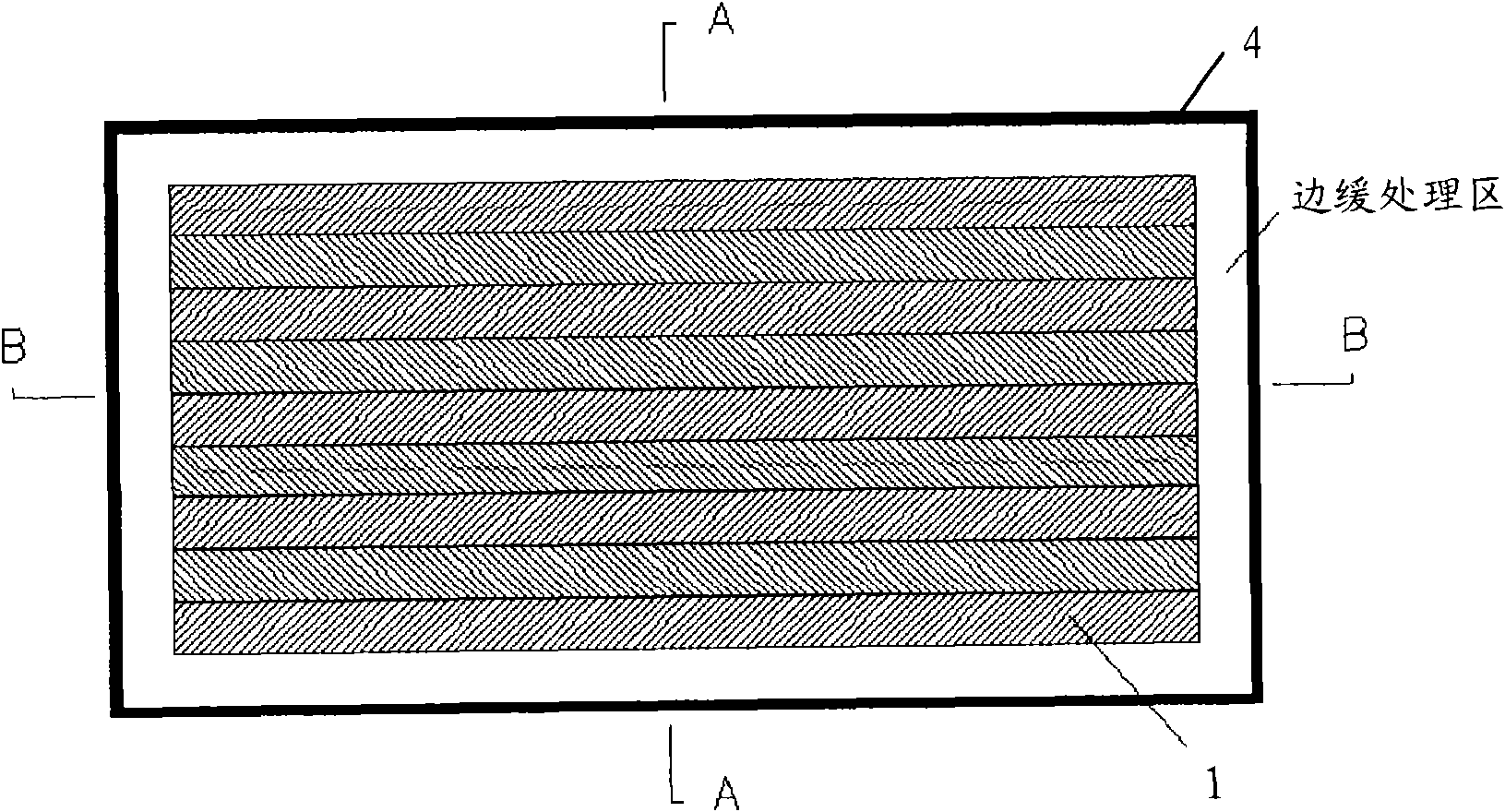
[0022] figure 1 It is the front top view of the solar cell module. exist figure 1 In , the solar cell module is shown in a rectangular surface appearance, but other shapes and sizes can be adopted according to actual needs. Looking down from the front of the solar cell module, the thin-film cells arranged in order can be seen through the light-receiving glass panel of the cell sheet. The area around the thin film battery is the edge treatment area.

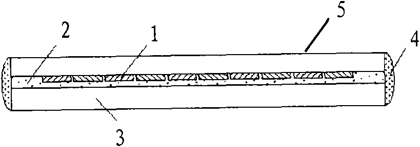
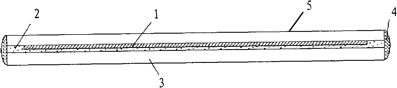
[0023] figure 2 yes figure 1 The cross-sectional view of t...


PUM


Abstract

The invention provides a thin film solar cell component encapsulation mode, including cutting off films at all the edges of thin film solar cells, superimposing and bonding the thin film solar cell component (1) with a lower bottom surface (3) by binding agent (2) to form a component, and smearing an outdoor aging resistant waterproof glue layer (4) with appropriate thickness. The laminated structure not only causes the thin film solar cell to be effectively protected and have better pollution resistance, damp resistance and mechanical damage resistance performances but also ensures luminousness to be enough, so as to keep conversion efficiency of the cell; the outdoor aging resistant waterproof glue layer (4) is smeared at the edges, and the outdoor aging resistant waterproof glue layer not only can be used as a buffer layer to prevent the glass of the component from being broken by bump but also can prevent outside moisture and impurity from being directly contacted with the binding agent (2) on the section of the component, thus weatherability of the component is improved and the service life of the thin film solar cell is greatly prolonged.

Description

technical field [0001] The present invention relates to a thin-film solar cell module capable of solar power generation and its packaging method which is arranged on the roof or outer wall of a building. Background technique [0002] Solar photovoltaic power generation is one of the important ways to obtain renewable and clean energy that is beneficial to the environment, and thin-film solar cells represent the development trend of photovoltaic technology. [0003] Solar cell modules are often used as solar power generation systems installed on roofs or exterior walls of buildings to supplement household electricity. The solar cell module is used outdoors for a long time, and its outer package is required to have good weather resistance. At present, the method of encapsulating thin-film solar cells is mainly to directly laminate the cell sheet formed on the light-receiving glass panel by chemical vapor deposition and other methods with an adhesive to the lower bottom surfac...

Claims


Application Information

Patent Timeline
IPC IPC(8): H01L31/18H01L31/048H01L31/0203
CPCY02P70/50
Inventor 杨与胜庄辉虎
Owner GS SOLAR FU JIAN COMPANY
Why Eureka
Try Eureka