
Method for analyzing influence of idle impact load of electric arc furnace on grid

A technology of impact load and analysis method, applied in reactive power compensation, reactive power adjustment/elimination/compensation, electrical components, etc., it can solve the problem of large error in calculation results, low accuracy of flicker improvement rate, and failure to reflect Shock load and other problems, to achieve the effect of solving the uncertainty of change time, high accuracy and reduced degree of influence

Inactive Publication Date: 2009-12-30
JIANGSU KENENG ELECTRIC POWER ENG CONSULTING
View PDF0 Cites 10 Cited by
  • Summary
  • Abstract
  • Description
  • Claims
  • Application Information

AI Technical Summary

Problems solved by technology

Since the magnitude of the reactive power fluctuation at the PCC point cannot be known in actual calculations, and the formula fails to reflect the transient process of the impact load change, the above formula is usually not used to calculate the voltage fluctuation at the PCC point
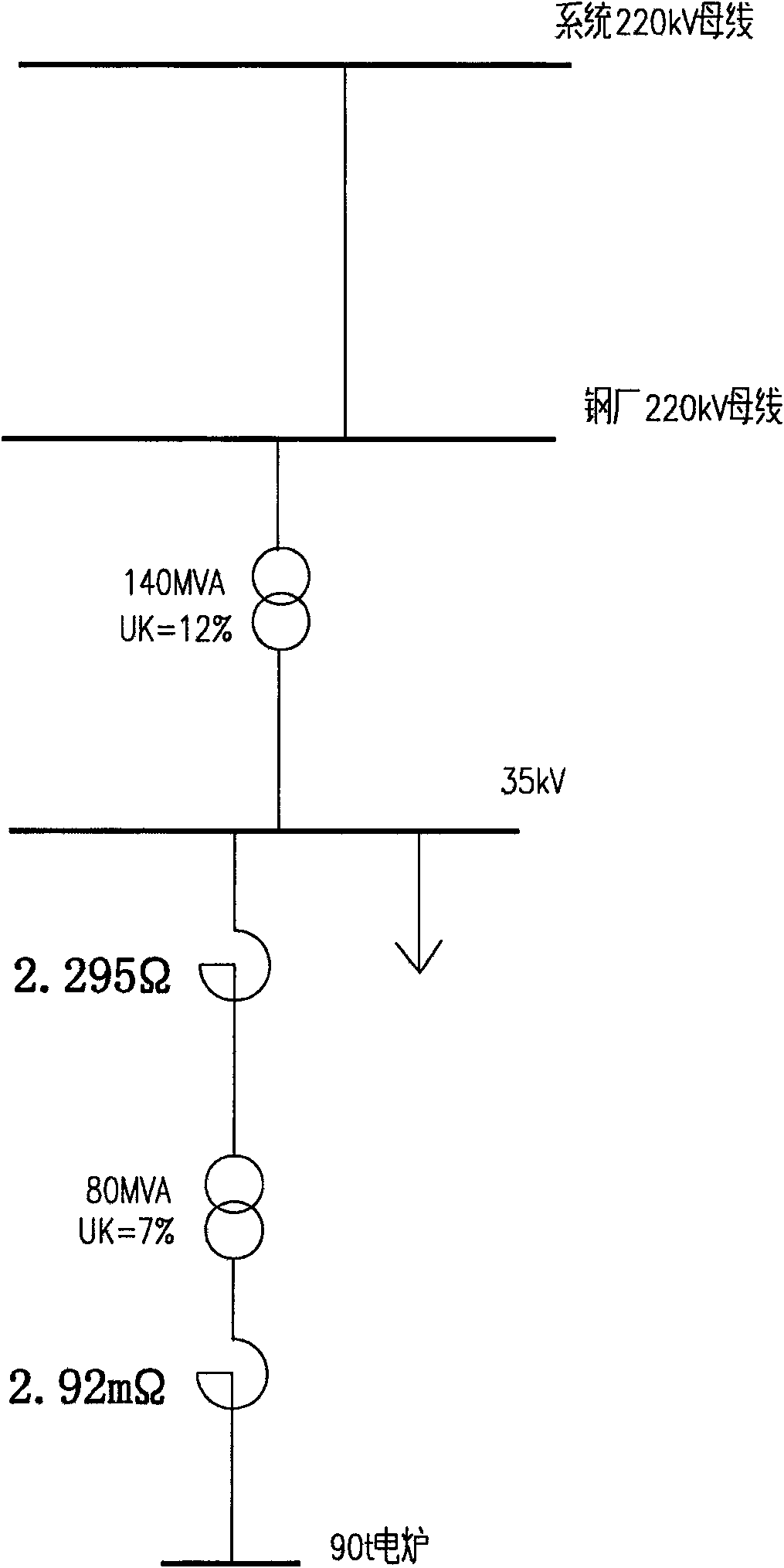
[0004] At present, the domestic electric power design institutes usually use the following method to calculate the voltage fluctuation caused by the AC electric arc furnace at the PCC point and the reactive power compensation capacity required to be installed as follows: apply the power system analysis comprehensive program PSASP, establish the electric arc furnace model in the program, and pass it in a short time Simulate a reactive impact load ΔQ on the grid impedance bus k and its change time Δt to calculate the voltage fluctuation at the PCC point; the limitation of this calculation method is that the simulated reactive impact load change time Δt cannot be determined, and if the predicted Δt differs greatly from the actual one, the error of the calculation result is also large , that is, the calculated flicker improvement rate has low accuracy, which in turn affects the calculation of reactive power compensation capacity

Method used


Image

  • Method for analyzing influence of idle impact load of electric arc furnace on grid
  • Method for analyzing influence of idle impact load of electric arc furnace on grid

Examples


Embodiment Construction

[0013] The maximum reactive impact load of the electric arc furnace refers to the maximum reactive power fluctuation value increased from normal smelting to working short circuit. Therefore, the moment when the maximum reactive impact load occurs in the electric arc furnace is equivalent to the impedance short circuit of the short network of the electric arc furnace. According to this, the present invention is:

[0014] A. Establish an electric arc furnace model in the PSASP program, and obtain the maximum reactive power impact load of the electric arc furnace through a three-phase short circuit on the short grid impedance bus, and then obtain the voltage fluctuation and flicker of the public access point PCC;

[0015] B. According to the national standard and the obtained voltage fluctuation and flicker of PCC point, the improvement rate of reactive power impact load is obtained.

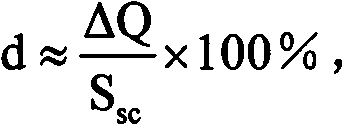
[0016] In step A, by the formula The maximum reactive impact load of the electric arc furnace ...


PUM


Abstract

The invention relates to a method for analyzing the influence of an idle impact load of an electric arc furnace on a grid, which applies a power system analysis software package PSASP. The method comprises the following steps: A, establishing an electric arc furnace model in the PSASP and installing three-phase short-circuit in a short network impedance bus to obtain voltage fluctuation and flicker of a point of common coupling PCC; and B, obtaining the improvement rate of the idle impact load according to the national standard requirements and the obtained voltage fluctuation and flicker of the PCC. The method fundamentally solves the problem of uncertain change time of the idle impact load of the electric arc furnace and determines high accuracy of the improvement rate of the flicker. The method is reasonable, reduces the influence of the impact load on the grid to the maximum and ensures secure and stable operation of the grid and high-quality electric energy quality.

Description

technical field [0001] The invention relates to the analysis of the influence of nonlinear impact loads such as an electric arc furnace on the power quality, voltage fluctuation and flicker of the power grid, and is an analysis method for the influence of the reactive impact load of the electric arc furnace on the power grid. Background technique [0002] During the operation of the AC electric arc furnace, especially during the melting period, the random and large fluctuations in reactive power will cause serious fluctuations in the voltage of the power supply bus, which will cause harm to electrical equipment, and the flashing lights will cause visual fatigue to the human eye. In order to make the voltage fluctuation value of the public access point PCC meet the national standard, measures need to be taken to install a dynamic static var compensation device (Static Var Compensation, SVC). [0003] According to GB 12326-2000 "Power Quality Voltage Fluctuation and Flicker", ...

Claims


Application Information

Patent Timeline
Patent Type & Authority Applications(China)
IPC IPC(8): H02J3/00H02J3/18G06F17/50
CPCY02E60/76Y04S40/22Y02E40/30
Inventor 胡煜肖凌
Owner JIANGSU KENENG ELECTRIC POWER ENG CONSULTING
Learn More