
Manufacturing method of resistance strain gage based on ion beam technology

A technology of resistance strain gauge and manufacturing method, which is applied in microstructure technology, electric/magnetic solid deformation measurement, photoengraving process of pattern surface, etc., can solve the problems of poor repeatability, strict material requirements, complex process, etc. The effect of high rate, large elastic coefficient and simple process

Inactive Publication Date: 2009-12-30
SHAANXI ELECTRICAL APPLIANCE RES INST
View PDF0 Cites 25 Cited by
  • Summary
  • Abstract
  • Description
  • Claims
  • Application Information

AI Technical Summary

Problems solved by technology

This process has a series of shortcomings such as demanding materials, complicated process, and poor repeatability.

Method used


Image

  • Manufacturing method of resistance strain gage based on ion beam technology
  • Manufacturing method of resistance strain gage based on ion beam technology
  • Manufacturing method of resistance strain gage based on ion beam technology

Examples


Embodiment Construction

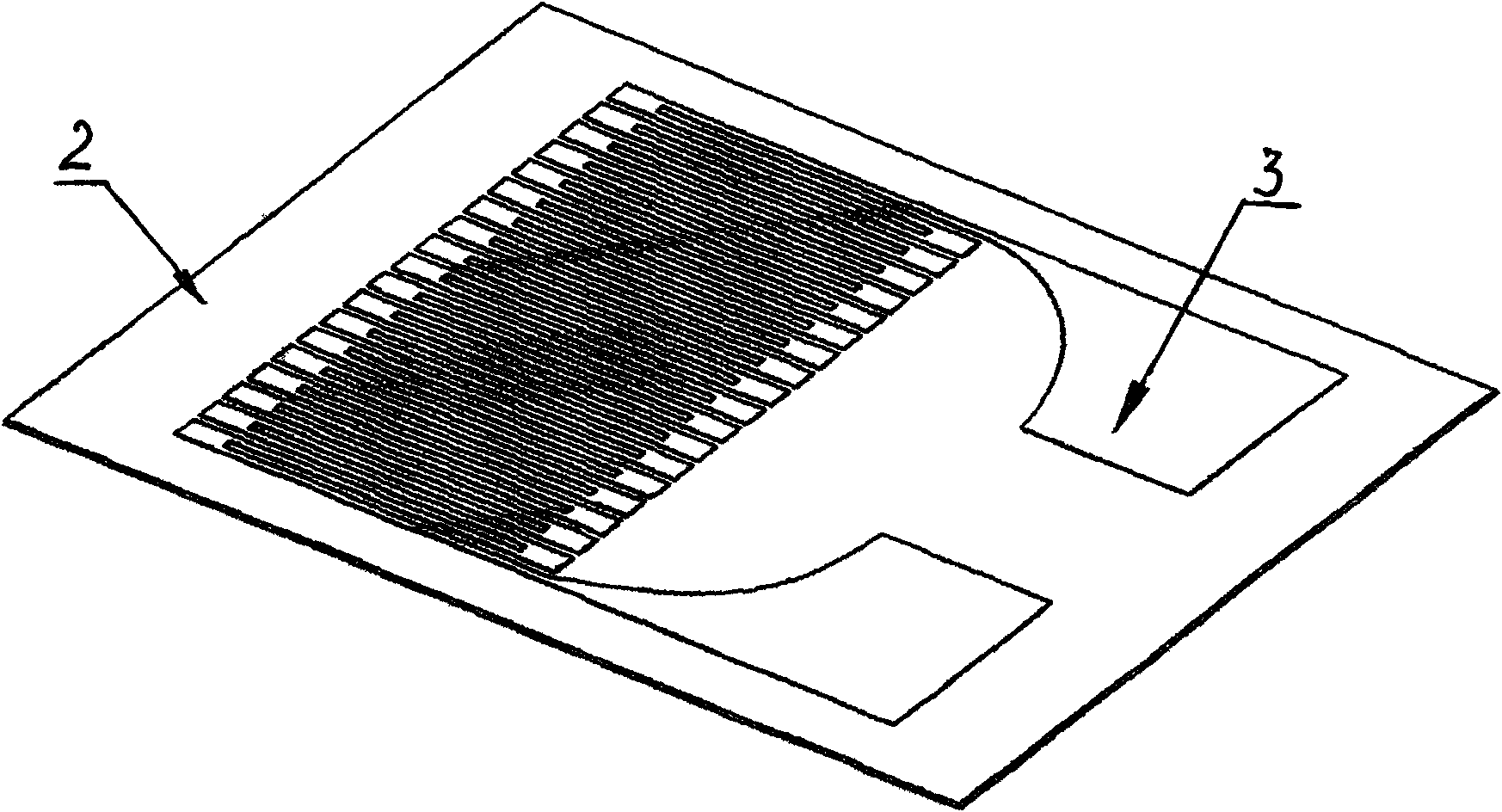
[0021] Referring to the accompanying drawings, the manufacturing method of the resistance strain gauge based on the ion beam technology provided by the present invention includes the process steps of preparing a flexible substrate, making a resistance alloy film, preparing circuit patterns and etching patterns by photolithography, and a specific manufacturing example is as follows stated.

[0022] 1. Preparation of flexible substrate

[0023] High-temperature silicone rubber substrate with a thickness of 1-3mm ( figure 2 ), first clean the substrate with alcohol and deionized water, bake it in a convection oven at 100°C for 10 minutes, dry it, and then place a supporting metal (stainless steel) frame with a thickness of 1 to 2 mm on the surface of the substrate. The inside of the frame is coated with diluted polyimide acid glue with a thickness of 0.5-1.5mm by means of scraping glue, and the scraper is used to scrape evenly in one direction at a time, and the glue is placed ...


PUM

PropertyMeasurementUnit
Thicknessaaaaaaaaaa
Thicknessaaaaaaaaaa

Abstract

The invention relates to a manufacturing method of a resistance strain gage based on an ion beam technology. The method comprises the following steps: coating polyimide glue solution on the surface of a high temperature silicon rubber substrate by adopting a DC plasma sputtering technology and a plasma etching technology, hot solidifying the polyimide glue solution to form a flexible polyimide substrate, then peeling off, solidifying to obtain a flexible substrate film with needed strain property requirement, sputtering a resistance alloy film on the polyimide surface of the flexible substrate and finally manufacturing the resistance strain gage by a photoengraving and etching process. The invention has simple process, high rate of finished products, controllable components of the resistance alloy film, adjustable alloy components as required, high image resolution, favorable property of manufactured material, and the like.

Description

technical field [0001] The content of the present invention belongs to the technical field of manufacturing testing and measuring devices, and relates to a method for manufacturing a sensitive element for a resistance strain sensor—a miniature foil resistance strain gauge, which can be used to prepare a self-compensating resistance strain gauge with a temperature coefficient of resistance required by the user . Background technique [0002] Resistance strain gauges, also known as resistance strain gauges, include foil or miniature foil resistance strain gauges, which are resistance strain sensitive elements and can be used to measure unidirectional or multidirectional strain values ​​on the surface of various components. The resistance strain gauge is mainly composed of a sensitive grid and a substrate. The sensitive grid is the most important part of the resistance strain gauge, and its function is to convert the strain of the elastic element into the resistance change; th...

Claims


Application Information

Patent Timeline
IPC IPC(8): G01B7/16B81C1/00G03F7/00
Inventor 黎明诚戚龙盖广洪
Owner SHAANXI ELECTRICAL APPLIANCE RES INST
Learn More