An engine gas distribution system with electro-hydraulic integrated control

A comprehensive control and engine technology, applied in the direction of engine components, machines/engines, mechanical equipment, etc., can solve problems such as difficult to adjust valve overlap angle, easy wear, complex structure, etc., to achieve optimized engine performance, flexible control, and long service life Effect

Inactive Publication Date: 2011-11-30
ZHEJIANG UNIVERSITY OF SCIENCE AND TECHNOLOGY
View PDF3 Cites 0 Cited by
  • Summary
  • Abstract
  • Description
  • Claims
  • Application Information

AI Technical Summary

Problems solved by technology

[0003] The present invention mainly solves the technical problems existing in the prior art such as complex structure, easy wear, and difficulty in adjusting valve overlap angle, etc., and provides a valve with simple structure, long service life, and electro-hydraulic comprehensive control to achieve the best gas distribution effect. Comprehensive control device for engine gas distribution system

Method used


Image

  • An engine gas distribution system with electro-hydraulic integrated control
  • An engine gas distribution system with electro-hydraulic integrated control
  • An engine gas distribution system with electro-hydraulic integrated control

Examples


Embodiment 1

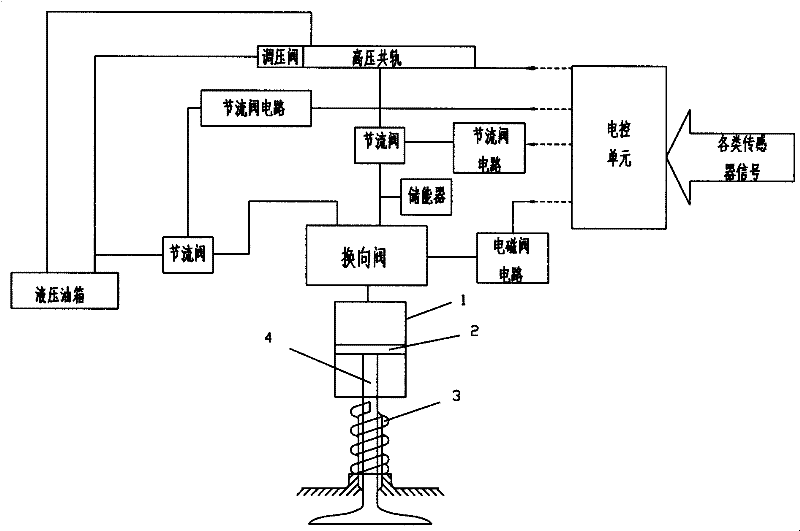
[0020] attached figure 1 It is a structural diagram of the present invention, it has a hydraulic cylinder 1, the piston rod 4 of the hydraulic cylinder is connected with the valve stem, and a pressure spring 3 is housed and connected with the valve stem. The oil circuit of the hydraulic cylinder is connected with a reversing valve, which is a 2-position 3-way valve, and is connected with the electronic control unit through a solenoid valve circuit. One of its valve positions is connected with the high-pressure oil circuit, and the other valve position is connected with the low-pressure circuit. A throttle valve is arranged on the high-pressure oil circuit, and the throttle valve is connected with the electronic control unit through a throttle valve circuit. An accumulator communicates with it on the oil circuit between the throttle reversing valves. The high-pressure oil route is powered by the high-pressure common rail system of the diesel engine, and has a pressure regulat...

Embodiment 2

[0023] attached figure 2 It is a kind of structure schematic diagram of the present utility model, and it has a hydraulic cylinder 1 similarly with embodiment 1, and the piston rod 4 of hydraulic cylinder links to each other with valve stem, and a pressure spring 3 is housed and connected on the valve stem. The oil circuit of the hydraulic cylinder is connected with a reversing valve, which is a 2-position 3-way valve, and is connected with the electronic control unit through a solenoid valve circuit. One of its valve positions is connected with the high-pressure oil circuit, and the other valve position is connected with the low-pressure circuit. A throttle valve is arranged on the high-pressure oil circuit, and the throttle valve is connected with the electronic control unit through a throttle valve circuit. An accumulator communicates with it on the oil circuit between the throttle reversing valves. A throttle valve is arranged on the low-pressure oil circuit, and the th...


PUM


Abstract

The invention relates to an engine gas distribution system, in particular to an engine inlet (exhaust) valve control device. It includes a valve stem, a hydraulic cylinder and a hydraulic oil circuit. The piston rod of the hydraulic cylinder is connected to the valve rod, and the oil inlet is connected to the oil circuit of a reversing valve. The low-pressure circuit is connected, and the reversing valve is controlled by an electromagnetic switch. The hydraulic oil cylinder is realized through a reversing valve or is connected with a high-pressure oil circuit, or is connected with a low-pressure circuit. When the hydraulic cylinder is connected to the high-pressure oil circuit, oil starts to enter, the piston moves downward, and the valve opens; when the hydraulic cylinder is connected to the low-pressure circuit, oil begins to return, the piston moves upward, and the valve gradually closes. The conversion of the reversing valve is controlled by an electromagnetic switch, so as long as the opening and closing of the electromagnetic valve is controlled, the opening and closing of the valve can be realized. The invention has the characteristics of simple structure, convenient production and processing, flexible control, long service life and low cost.

Description

technical field [0001] The invention relates to an engine gas distribution system, in particular to an engine inlet (exhaust) valve control device. Background technique [0002] The traditional engine gas distribution mechanism mainly has a set of complex transmission mechanism, which consists of transmission chain (or timing belt, tappet), timing chain (belt) tensioning mechanism, timing sprocket (or timing gear), camshaft , rocker arm, rocker pin, valve, valve guide, valve spring and other components. The valve timing of the engine directly affects the intake and exhaust performance, and plays a vital role in the combustion process. The choice of valve timing should not only take into account the engine's high-speed power, low-speed torque, idling fuel consumption, and fuel economy under partial load, but also take into account low-speed stability and exhaust emissions. The structure of the traditional cam-type engine valve transmission mechanism is complex, easy to wear...

Claims


Application Information

Patent Timeline
Patent Type & Authority Patents(China)
IPC IPC(8): F01L9/02F01L9/10
Inventor 程峰李强杨礼康唐智宏
Owner ZHEJIANG UNIVERSITY OF SCIENCE AND TECHNOLOGY
Why Eureka
Try Eureka