
Ultrasonic cystoscope

A technology of cystoscopy and ultrasound, applied in the fields of cystoscopy, urethroscopy, medical science, etc., can solve the problem of no bladder diagnosis and treatment technology, only 1 to 2 instrument channels, and inability to provide information on lesions of various layers of the bladder and surrounding organs, etc. question

Active Publication Date: 2009-12-23
GUANGZHOU BAODAN MEDICAL INSTR TECH
View PDF0 Cites 20 Cited by
  • Summary
  • Abstract
  • Description
  • Claims
  • Application Information

AI Technical Summary

Problems solved by technology

[0002] At present, cystoscopy and cystoscopy technology have been widely used clinically, and are important tools for diagnosis and treatment of diseases in urology. However, the existing cystoscopy used for the diagnosis and treatment of bladder diseases can determine the lesion of the bladder, but cannot understand the layers of the bladder and its surroundings. Changes in organs, there are hidden dangers of insufficient diagnostic accuracy, and there are only 1 to 2 instrument channels, and more complicated operations cannot be performed
At present, in clinical medicine, the understanding of bladder lesions mainly relies on extracorporeal B-ultrasound and CT techniques, which cannot provide more accurate information on the lesions of each layer of the bladder and surrounding organs.
In addition, the current ultrasonic endoscopic technology has been widely used in gastric, duodenal and other surgical fields, and its equipment is various types of soft mirrors and supporting miniature ultrasonic probes, etc., but it has not been used in the diagnosis and treatment of bladder

Method used


Image

  • Ultrasonic cystoscope
  • Ultrasonic cystoscope
  • Ultrasonic cystoscope

Examples


Embodiment Construction

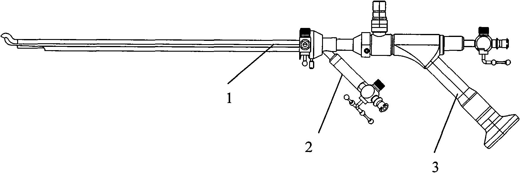
[0027] The present invention as figure 1 , combined with figure 2 , Figure 6 and Figure 8 As shown, the ultrasonic cystoscope of the present invention is composed of an ultrasonic cystoscope sheath 1 , a manipulator 2 , an endoscope main body 3 and a miniature ultrasonic probe 4 .

[0028] Such as image 3 , Figure 4 As shown, in the present invention, the specific parts of the mirror sheath 1 include a sheath tube end 12 , liquid passages 13 , 14 , and a locking device 15 . In addition, the tip portion 11 of the mirror sheath 1 is designed as a blunt structure, that is, a non-destructive design, which can effectively avoid damaging the urethra when the mirror sheath 1 enters the urethra. In the present invention, the length of the end 12 of the mirror sheath 1 is designed to be 180-220 mm, and the shape of the end 12 is non-circular, with a maximum diameter of 8.4 mm and a minimum diameter of 6.6 mm.

[0029] Such as Figure 5 As shown, the ultrasonic cystoscope sh...


PUM

PropertyMeasurementUnit
Lengthaaaaaaaaaa
The maximum diameteraaaaaaaaaa
Minimum diameteraaaaaaaaaa

Abstract

The invention discloses an ultrasonic cystoscope which belongs to the technical field of medical apparatuses. The ultrasonic cystoscope is formed by organically combing an altered scleroid cystoscope with a miniature ultrasonic probe, and has the functions of a cystoscope and ultrasonic inspection. The ultrasonic cystoscope comprises an endoscope main body. The endoscope main body comprises a scleroid endoscope end part, and an apparatus passage, a cold light source input end and an eye lens input end which are communicated with the scleroid endoscope end part. A lens sheath is arranged outside the endoscope main body, and an operator with at least one apparatus passage is connected with the lens sheath. The miniature ultrasonic probe used for carrying out real-time ultrasonic scanning on bladders is arranged in the apparatus passage of the endoscope main body. The ultrasonic cystoscope can exactly fix the position, the size, the appearance and the range of focus, enhance the accuracy of bladder examination, diagnosis and operation, make up the shortage of the current diagnosis and treat methods and better diagnose and treat various bladder diseases. In addition, the ultrasonic cystoscope has favorable grippage, which is convenient for operations to be carried out successfully.

Description

technical field [0001] The invention belongs to the technical field of medical instruments. In particular, it relates to a core medical tool for carrying out urological surgery in modern medicine, that is, an ultrasonic cystoscope. Background technique [0002] At present, cystoscopy and cystoscopy technology have been widely used clinically, and are important tools for diagnosis and treatment of diseases in urology. However, the existing cystoscopy used for the diagnosis and treatment of bladder diseases can determine the lesion of the bladder, but cannot understand the layers of the bladder and its surroundings. There are hidden dangers of insufficient diagnostic accuracy due to changes in organs, and there are only 1 or 2 instrument channels, so more complicated operations cannot be performed. At present, in clinical medicine, the understanding of bladder lesions mainly relies on in vitro B-ultrasound and CT techniques, which cannot provide more accurate information on t...

Claims


Application Information

Patent Timeline
IPC IPC(8): A61B8/12A61B1/307
Inventor 乔铁张阳德张宝善黄万潮谢景夏何群芝
Owner GUANGZHOU BAODAN MEDICAL INSTR TECH
Learn More