
Shift register and grid line drive device thereof

A technology of shift registers and gates, applied in static memory, digital memory information, instruments, etc., can solve problems such as short life and unstable work, and achieve the effects of reducing damage, reducing working time, and reducing damage

Active Publication Date: 2009-12-16
BEIJING BOE OPTOELECTRONCIS TECH CO LTD
View PDF0 Cites 48 Cited by
  • Summary
  • Abstract
  • Description
  • Claims
  • Application Information

AI Technical Summary

Problems solved by technology

[0006] The purpose of the present invention is to provide a shift register and its gate line driving device, which can effectively solve the technical defects of the prior art such as unstable operation and short life due to long-term continuous application of high voltage to the gate of the thin film transistor.

Method used


Image

  • Shift register and grid line drive device thereof
  • Shift register and grid line drive device thereof
  • Shift register and grid line drive device thereof

Examples


Embodiment Construction

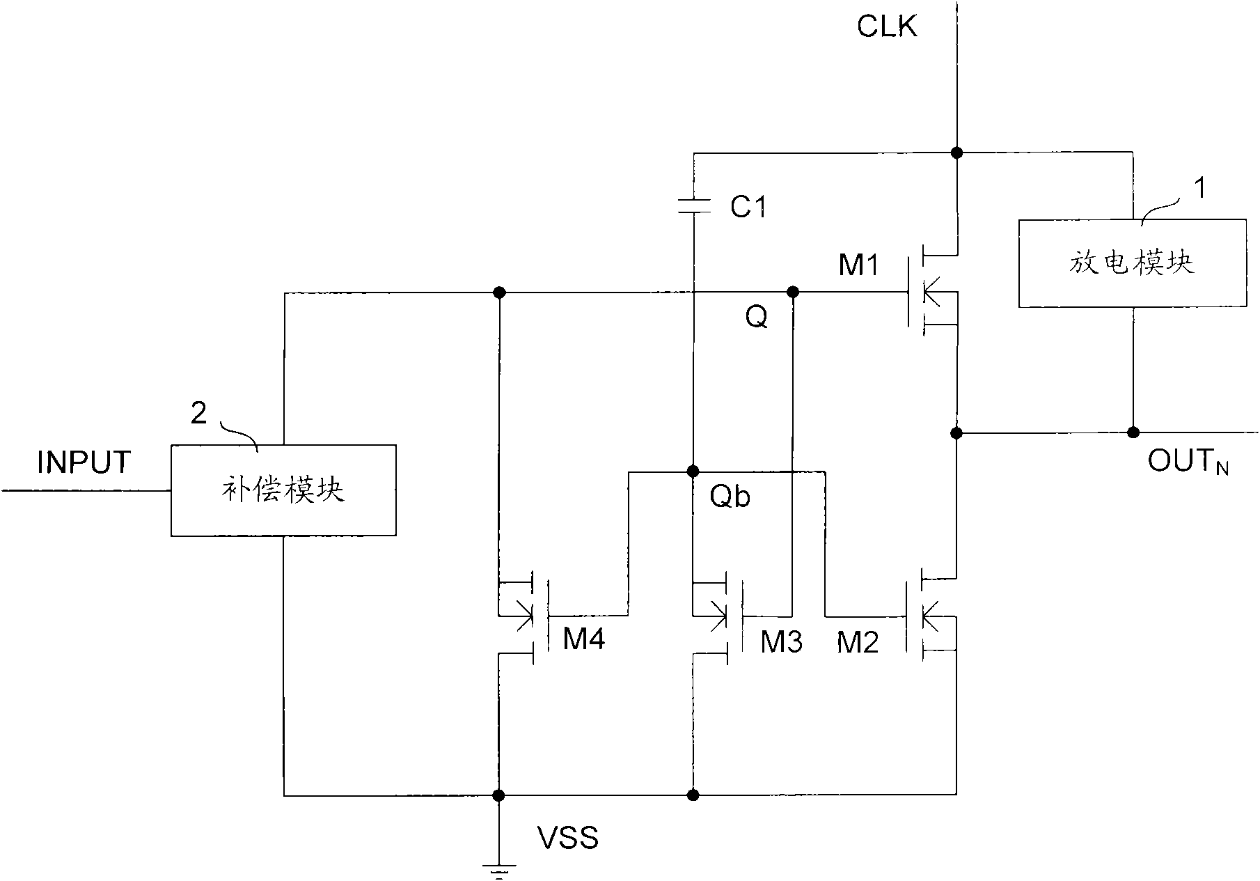
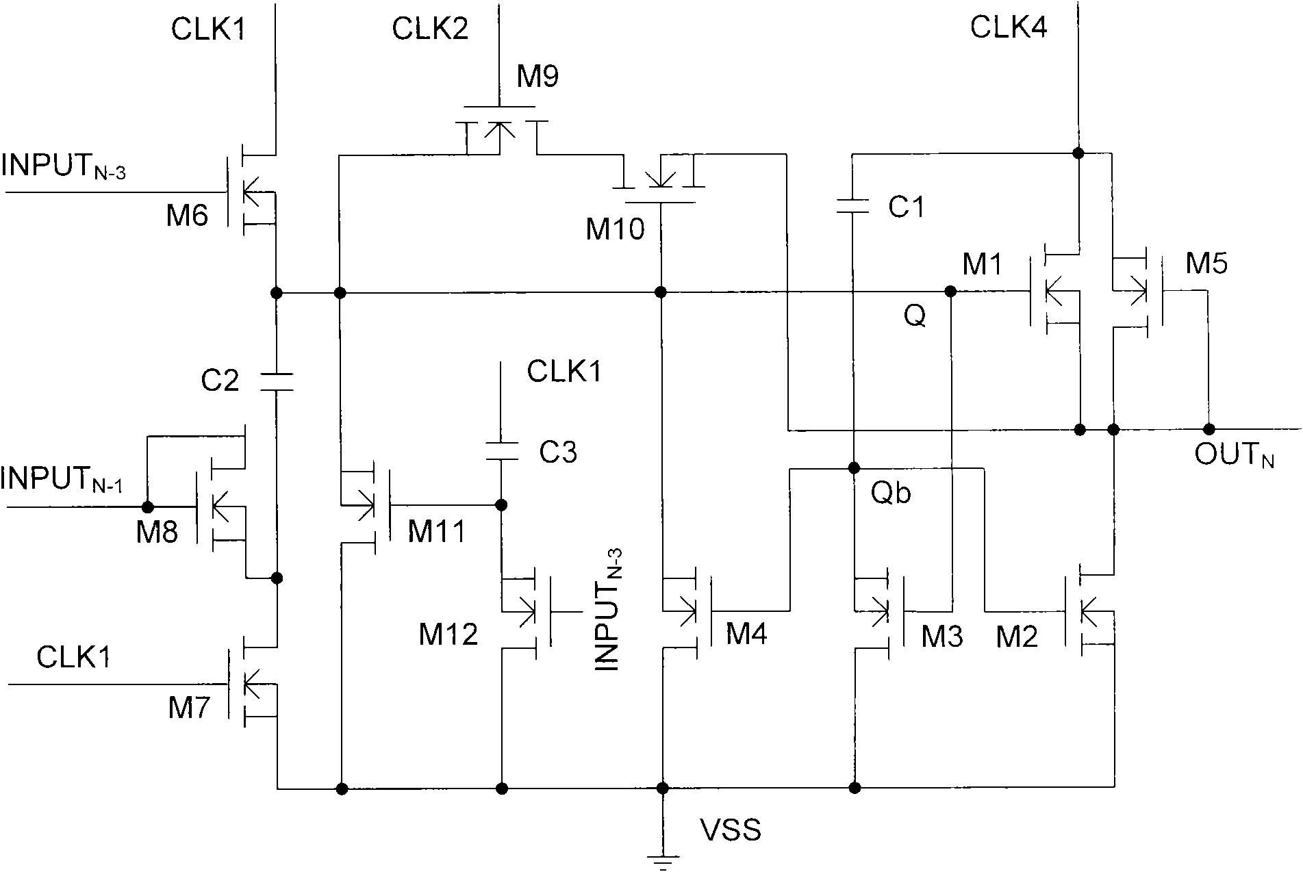
[0051] figure 1 It is a structural schematic diagram of the shift register of the present invention. Such as figure 1 As shown, the main body of the shift register of the present invention includes four thin film transistors, a storage capacitor, a discharge module, a compensation module and corresponding input and output terminals, wherein the gate of the first thin film transistor M1 is connected to the first pull-up node A node Q is connected, its source is connected to a clock signal terminal CLK, and its drain is connected to the output terminal OUT of this stage N connection, its role is to provide the stage output OUT N Provide a high-level output; the gate of the second thin film transistor M2 is connected to the second node Qb as a pull-down node, and its source is connected to the output terminal OUT of the current stage N Its drain is connected to the low-level signal terminal VSS, and its function is to keep the output terminal OUT of this stage N is low leve...


PUM


Abstract

The invention relates to a shift register and a grid line drive device thereof. The shift register comprises a first thin film transistor, a second thin film transistor, a third thin film transistor, a fourth thin film transistor, a first capacitor, a discharge module and a compensation module. A gird of the first thin film transistor is connected with a first node, a source electrode of the first thin film transistor is connected with a clock signal end, and a drain electrode of the first thin film transistor is connected with a same-level output end; a grid of the second thin film transistor is connected with a second node, a source electrode of the second thin film transistor is connected with the same-level output end, and a drain electrode of the second thin film transistor is connected with a low level signal end; a grid of the third thin film transistor is connected with the first node, a source electrode of the third thin film transistor is connected with the low level signal end, and a drain electrode of the third thin film transistor is connected with the second node; a grid of the fourth thin film transistor is connected with the second node, a source electrode of the fourth thin film transistor is connected with the low level signal end, and a drain electrode of the fourth thin film transistor is connected with the first node; the first capacitor is connected between the clock signal end and the second node; the discharge module is connected between the clock signal end and the same-level output end; and the compensation module is connected between the first node and the low level signal end. The invention has the advantages of low cost, low power consumption, long service life, high stability, strong interference resistance, small delay, and the like.

Description

technical field [0001] The invention relates to a driving device of a liquid crystal display, in particular to a shift register and a gate line driving device thereof. Background technique [0002] Liquid crystal display (LCD) has the characteristics of light weight, thin thickness and low power consumption, and is widely used in devices such as mobile phones, monitors, and televisions. The liquid crystal display uses an electric field to control the deflection of the liquid crystal, so as to control the transmission of light to form a display screen. The liquid crystal display is mainly composed of a pixel matrix arranged in two directions, horizontal and vertical. The horizontal part of the pixel array is composed of grid lines, and consists of The shift register provides gate line driving signals, and the vertical part of the pixel array is composed of data lines, which are used to apply data signals to the pixel array, and the required electric field is formed by applyin...

Claims


Application Information

Patent Timeline
Patent Type & Authority Applications(China)
IPC IPC(8): G11C19/28G09G3/36
CPCG11C19/28G02F1/133G09G3/36H03K19/00
Inventor 胡明
Owner BEIJING BOE OPTOELECTRONCIS TECH CO LTD
Learn More