
Solar heating system for building with cast-in-situ open-web floor

A fasting floor and heating system technology, applied in the field of energy-saving buildings, can solve the problems of high heating costs, large energy waste, and unreasonable arrangements

Inactive Publication Date: 2009-12-16
王本淼 +1
View PDF4 Cites 66 Cited by
  • Summary
  • Abstract
  • Description
  • Claims
  • Application Information

AI Technical Summary

Problems solved by technology

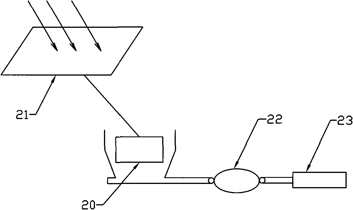
[0004] On the basis of its aforementioned application, the applicant proposes a utilization method that is high in efficiency, low in cost, safe, reliable, fast and convenient, and improves the use of space in order to solve the problems of high heating costs, space occupation, unreasonable arrangement, and large energy waste in buildings. The new technology scheme, this scheme adopts the following method: a heating system for a building with a cast-in-place hollow floor using solar energy, including a heating device and a circulation device, the circulation device is composed of a cast-in-place hollow floor, and the hollow floor includes The thin-walled box, the main girder between the thin-walled boxes, the rib beam, the upper flange plate above the thin-walled box, and the lower flange plate below, the side of the thin-walled box has at least two communication holes, each of the thin-walled boxes forms a dark anti-smoke exhaust pipe in the floor by inserting the connection channels of the communication holes on adjacent sides, and the improvement is that the heating device includes a light concentrating device, a heat receiver, The fan, the concentrating device includes a light source tracking turret, a light source tracking guide and a concentrating chip installed on the light source tracking turret, the thermal energy receiver is located at the focal point of the concentrating chip, and the fan is located at the thermal energy receiving side of the device,

Method used


Image

  • Solar heating system for building with cast-in-situ open-web floor
  • Solar heating system for building with cast-in-situ open-web floor
  • Solar heating system for building with cast-in-situ open-web floor

Examples


Embodiment Construction

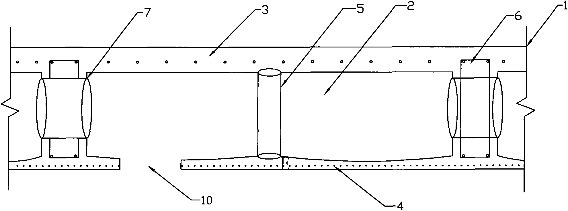
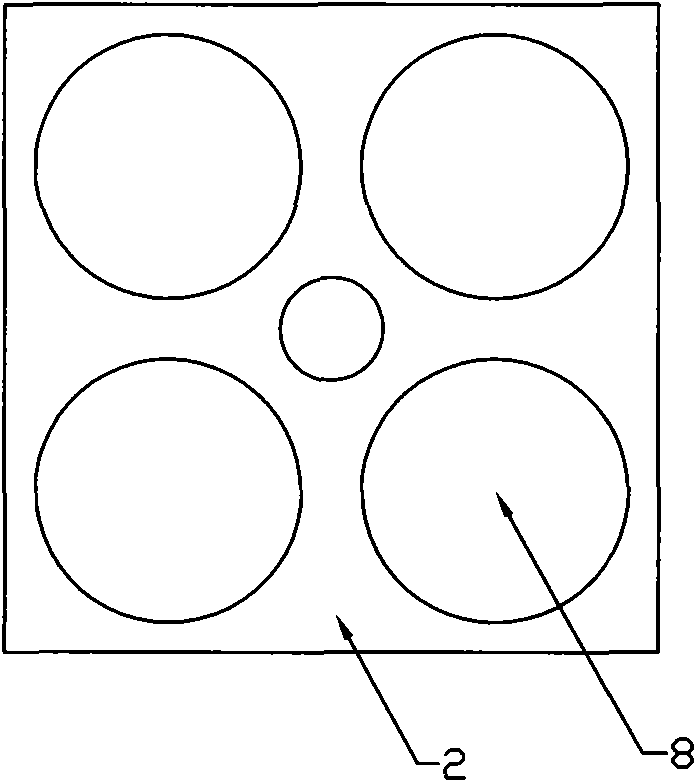
[0024] Such as figure 1 As shown, the schematic diagram of the cast-in-place hollow floor and the thin-walled box inside, the floor 1 includes the thin-walled box 2 in the middle, the upper flange plate 3, the rib beam 6, the lower flange plate 4 and the floor formwork, the thin-walled box There are several wall boxes 2 and they are cast-in-place with composite cement slurry or assembled from plates. An arc, the priority premise is to maintain balance. The bottom plate and the top cover are provided with opposite lower holes and upper holes, the lower holes on the bottom plate are connected with the upper holes on the top cover through a closed through passage 5, and the thin-walled boxes 2 are communicated through a connecting passage 7 installed on the side. A hot air circulation duct is formed inside the whole floor. The present invention will be further described below in conjunction with the accompanying drawings.

[0025] The thin-walled box 2 used in this program can...


PUM

PropertyMeasurementUnit
Heightaaaaaaaaaa

Abstract

The invention relates to a solar heating system for a building with a cast-in-situ open-web floor, which belongs to a system for providing heat for the building by using solar energy. In the proposal, sunlight is focused on a heat energy receiver by a concentration chip, and then hot air generated by the heat energy receiver is blown to the floor by a fan. The floor is formed by cast-in-situ of thin-walled box bodies; the thin-walled box bodies form a hot air cycle channel in the floor by using connecting channels; the hot air heats the floor after entering the floor, so the entire floor becomes a heat dissipating integration. The lower part of the thin-walled box bodies is provided with an air outlet leading to a room; when the air outlet is opened, the hot air is discharged to the room directly to heat the room quickly. The proposal makes use of the energy of the nature, so the solar heating system is clean and environment-friendly and saves cost and power; besides, the proposal makes full use of own structural characteristics of the building to avoid the problems of installation of additional devices and space occupation.

Description

technical field [0001] The invention relates to an energy-saving building, in particular to a system for heating a building by using solar energy and a cast-in-place hollow floor. Background technique [0002] At present, in terms of heating methods for buildings, most buildings install radiators in the rooms and use gas heating and water heating for heating. Maintenance, if there is a problem with the heating pipe in a building, almost the entire building has no heating, and the specific heating time needs to be arranged uniformly, and it cannot be used reasonably according to the weather, time, and occupancy. More unfavorable for energy conservation. There are also some that use heating pipes buried in the floor of the building, and then use gas to circulate the heated water in the pipes to heat. The floor heating is clean and uses the principle of rising hot air to make full use of heat, but this method is mainly used for later decoration. The construction carried out i...

Claims


Application Information

Patent Timeline
IPC IPC(8): F24D5/00F24J2/38F24D5/02F24D5/08F24D12/02E04B5/48F24S50/20
CPCY02B10/20Y02B10/70Y02B30/14Y02E10/47Y02B30/00
Inventor 王本淼韩爱兴王海崴
Owner 王本淼
Learn More