
Design method based on machine vision inspection centring control device

A technology for machine vision detection and control devices, applied in measuring devices, guiding/positioning/alignment devices, optical devices, etc. issues of flexibility

Active Publication Date: 2009-12-09
CHINA NON-FERROUS METALS PROCESSING TECH CO LTD
View PDF0 Cites 22 Cited by
  • Summary
  • Abstract
  • Description
  • Claims
  • Application Information

AI Technical Summary

Problems solved by technology

This detection method can meet the alignment needs of production, but its structure is complex, the failure rate is high, and the detection position needs to be manually adjusted according to the strip width, and positioning and driving devices need to be configured
In the case of continuous production, the production efficiency is affected. The main reason is that the detection device has a small visual range and the automatic positioning of the edge of the strip is not realized.
At the same time, the processing platform of this type of device is mainly based on hardware, which lacks flexibility and cannot realize complex intelligent detection and control algorithms.

Method used

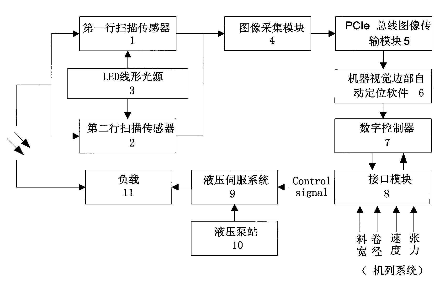

Image

  • Design method based on machine vision inspection centring control device
  • Design method based on machine vision inspection centring control device
  • Design method based on machine vision inspection centring control device

Examples


Embodiment Construction

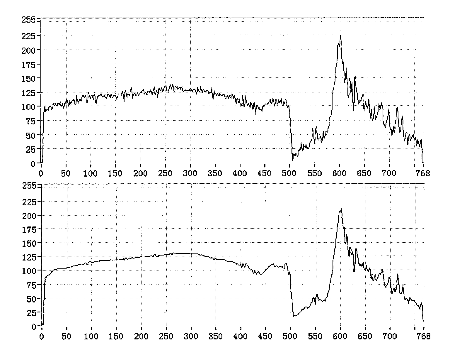
[0028] According to the process, the strip position measurement is divided into two processes. One is to overcome the problem of cylindrical distortion in the video collection method through synchronous linear acquisition of both sides; Adaptive recognition and tracking of the edge of the material; in addition, the vertical range of a detection can be customized due to the use of the first-scan technology, which overcomes the instability of the detection signal caused by the edge crack caused by simple line scanning, and overcomes the traditional video The size of the acquired image is fixed and the refresh cycle is low. In terms of implementation, virtual instrument software technology is used, and flexible and powerful computer software is used to replace some hardware of traditional instruments, so that intelligent detection algorithms can be realized in applications, especially the application of computers in the device directly participates in the generation and measuremen...


PUM


Abstract

The invention relates to a design method based on a machine vision inspection centring control device; a line scanning sensor senses wide long banding surfaces, and the result is output to an image acquisition module; LED linear light source generates convergent linear light which is irradiated on the object to be inspected, and surface condition is sent to the line scanning sensor; the image acquisition module carries out bottom layer treatment conversion on input signals of the line scanning sensor; a PCIe bus image transmission module provides point-to-point independent bandwidth bus channels for two routes of data of the image acquisition module; a machine vision margin automatically positioning software carries out positioning tracking on belting margin and calculates belt material centre deviation value; a digital controller determines parameters of the digital controller according to signals introduced by an interface module, and control signals are output to the interface module; the interface module inputs the signals of a system to the digital controller, and the result is output to a hydraulic servo system; the hydraulic servo system adjusts load moving speed according to the control signals output by the interface module; and a power unit supplies stressor.

Description

technical field [0001] The invention relates to a design method of a centering control device based on machine vision detection and belongs to the technical field of vision measurement and control. Background technique [0002] On the running production line, the strip should be aligned with the center line of the unit (or the set position) within a certain lateral tolerance range, otherwise it will cause damage to the equipment, stop production due to broken belt, and affect product quality. In order to ensure the safe operation of the strip on the production line, the centering control of the strip is required. The main components of the strip automatic centering control device include: detection system, microprocessor control device, driver and hydraulic control (or mechanical transmission) system . At present, there are several forms of centering and deviation correction: photoelectric, inductive, capacitive, and CCD. The detection device using CCD mostly adopts the way...

Claims


Application Information

Patent Timeline
IPC IPC(8): B21B39/14G01B11/00B65H23/032B65H26/00
Inventor 罗新斌邢青青黄秀琴王龙李坤杰郑文胜
Owner CHINA NON-FERROUS METALS PROCESSING TECH CO LTD
Learn More