
Liquid crystal display, active element array substrate and method for manufacturing active element array substrate

An active element and array substrate technology, which is applied in the field of array substrate and its manufacturing method and display device, can solve the problems of impedance rise, resistance-capacitance delay, increase of signal lines, etc., and achieve the effect of improving performance

Active Publication Date: 2009-12-02
INNOLUX CORP
View PDF2 Cites 7 Cited by
  • Summary
  • Abstract
  • Description
  • Claims
  • Application Information

AI Technical Summary

Problems solved by technology

However, when a voltage is applied to the scan line 104 and the data line 108, there will still be parasitic capacitance at the intersection 114, causing resistance-capacitance delay and affecting the display effect of the liquid crystal display device.
With the increase in the size of liquid crystal display devices, the data transmission speed is bound to increase, and the tolerance for resistance-capacitance delay is relatively poor.
Moreover, the length of the signal line also increases due to the increase in size, which in turn causes an increase in impedance, resulting in a higher resistance-capacitance delay

Method used


Image

  • Liquid crystal display, active element array substrate and method for manufacturing active element array substrate
  • Liquid crystal display, active element array substrate and method for manufacturing active element array substrate
  • Liquid crystal display, active element array substrate and method for manufacturing active element array substrate

Examples


Embodiment Construction

[0066] In the content described below, terms such as "first" and "second" added in front of each material layer are only used to separate different material layers, and do not represent the sequence of process steps or other meanings.

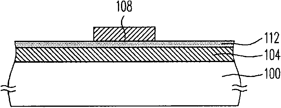
[0067] Figure 2A ~ Figure 2I What is shown is a partial cross-sectional view of the process steps of the active element array substrate according to an embodiment of the present invention, and Figure 3A-3F depicted as Figure 2A ~ Figure 2I Top view of some steps in the process.

[0068] Please refer to Figure 2A and Figure 3A , forming a first patterned conductive layer 210 on an insulating substrate 200 . Figure 2A yes Figure 3A Sectional view along line A-A. In the formation method of the first patterned conductive layer 210, for example, a complete conductive layer is first formed on the insulating substrate 200 by sputtering or other appropriate processes, and then the first photomask process is performed to pattern the conduct...


PUM


Abstract

The invention discloses a liquid crystal display, an active element array substrate and a method for manufacturing the active element array substrate. The method for manufacturing the active element array substrate comprises the following steps: forming a first patterned conductive layer on an insulating substrate provided with a plurality of scanning lines; forming an insulating layer covering the first patterned conductive layer on the insulating substrate; forming a patterned semiconductor on the insulating layer; forming a patterned insulating layer on the insulating layer; forming a second patterned insulating layer provided with a plurality of data lines and a plurality of source electrodes and drain electrodes on the insulating layer, which are connected with the data lines, wherein the data lines and the scanning liners intersect above the patterned insulating, and the source electrodes, the drain electrodes, the patterned semiconductor insulating layer, the insulating layer and the scanning lines form a plurality of active elements. In the invention, the resistance-capacitance delay is improved on the active elements.

Description

technical field [0001] The present invention relates to an array substrate, a manufacturing method thereof, and a display device, and in particular to an active component array substrate, a manufacturing method thereof, and a Liquid Crystal Display (LCD). Background technique [0002] The rapid progress of the multimedia society is mostly due to the rapid progress of semiconductor components or man-machine display devices. As far as display devices are concerned, flat panel display devices with superior characteristics such as high image quality, good space utilization efficiency, low power consumption, and no radiation have gradually become the mainstream of the market. Among various flat panel display devices, thin film transistor (Thin Film Transistor, TFT) liquid crystal display devices are currently the most mature flat panel display devices. [0003] However, there are still some problems to be improved in the development of the liquid crystal display device. One of t...

Claims


Application Information

Patent Timeline
IPC IPC(8): H01L21/84H01L21/768H01L27/12H01L23/522G02F1/1362G02F1/136
Inventor 许博文
Owner INNOLUX CORP
Learn More