
Adjustable electronic detonator control chip and flow for controlling same

A technology of electronic detonator and control chip, which is applied in the field of pyrotechnics manufacturing, can solve the problems of increasing the volume and cost of electronic detonators, affecting the delay accuracy of electronic detonators, and the explosion impact of unexploded detonators, so as to improve the flexibility of use and reliability. Integrated, reliable ignition effect

Active Publication Date: 2009-11-25
南通炜天电子科技有限公司
View PDF7 Cites 28 Cited by
  • Summary
  • Abstract
  • Description
  • Claims
  • Application Information

AI Technical Summary

Problems solved by technology

[0005] 1. Due to the fact that in the actual blasting application of electronic detonators, the delay time of each detonator is not the same, therefore, the first detonator will produce an explosive impact on the unexploded detonator
And because the crystal relies on its mechanical resonance to output a stable frequency to generate a clock, so when the reference clock circuit is taken as a crystal oscillator, the blasting shock wave will affect the resonant frequency of the crystal, thereby affecting the delay accuracy of the electronic detonator
In severe cases, the crystal may even be damaged by the explosion shock wave, thereby stopping the clock circuit and causing the detonator to fail
[0006] 2. The crystal used in the crystal oscillator cannot be integrated into the electronic detonator control chip, which increases the size and cost of the electronic detonator

Method used


Image

  • Adjustable electronic detonator control chip and flow for controlling same
  • Adjustable electronic detonator control chip and flow for controlling same
  • Adjustable electronic detonator control chip and flow for controlling same

Examples


Embodiment Construction

[0100] The technical solution of the present invention will be described in further detail below in conjunction with the accompanying drawings and specific embodiments.

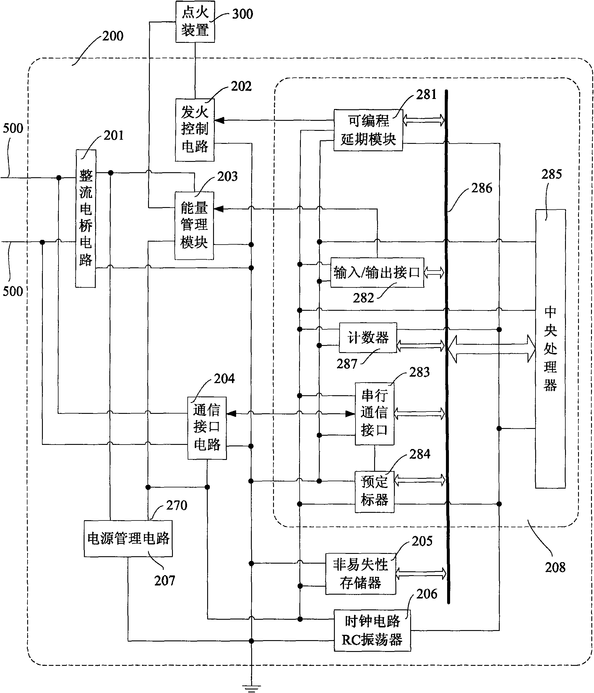
[0101] The present invention further improves on the basis of the patent application document 200810211374.2, and provides a calibrated electronic detonator control chip 200, such as figure 1 , including a rectifier bridge circuit 201 , an ignition control circuit 202 , an energy management module 203 , a communication interface circuit 204 , a power management circuit 207 , a nonvolatile memory 205 , a clock circuit, and a logic control circuit 208 . Wherein, the logic control circuit 208 includes a programmable delay module 281 , an input / output interface 282 , a serial communication interface 283 , a prescaler 284 , and a central processing unit 285 . One end of the clock circuit is grounded, one end is connected to the power output end 270 of the power management circuit 207 , and the other end is connect...


PUM


Abstract

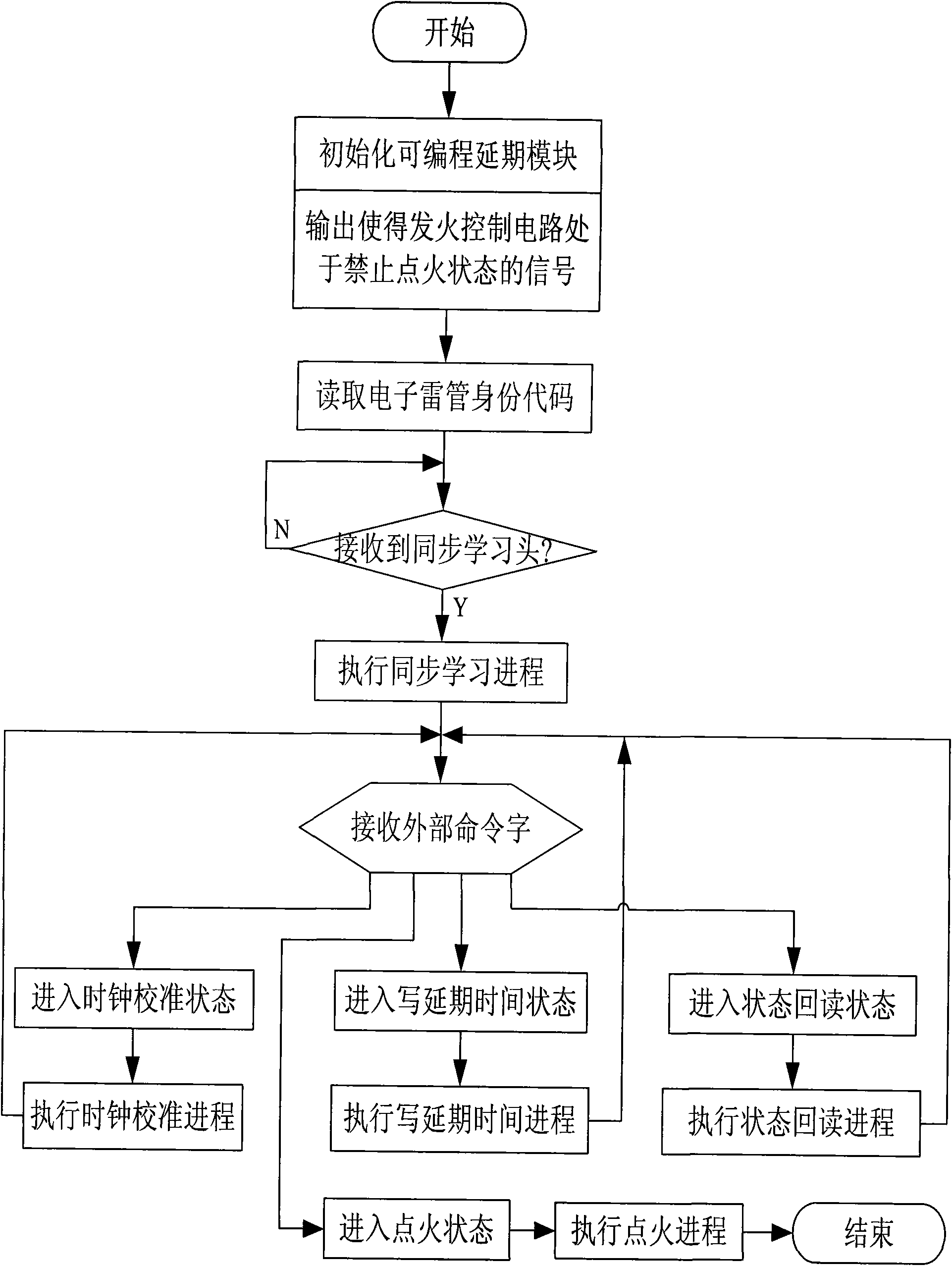
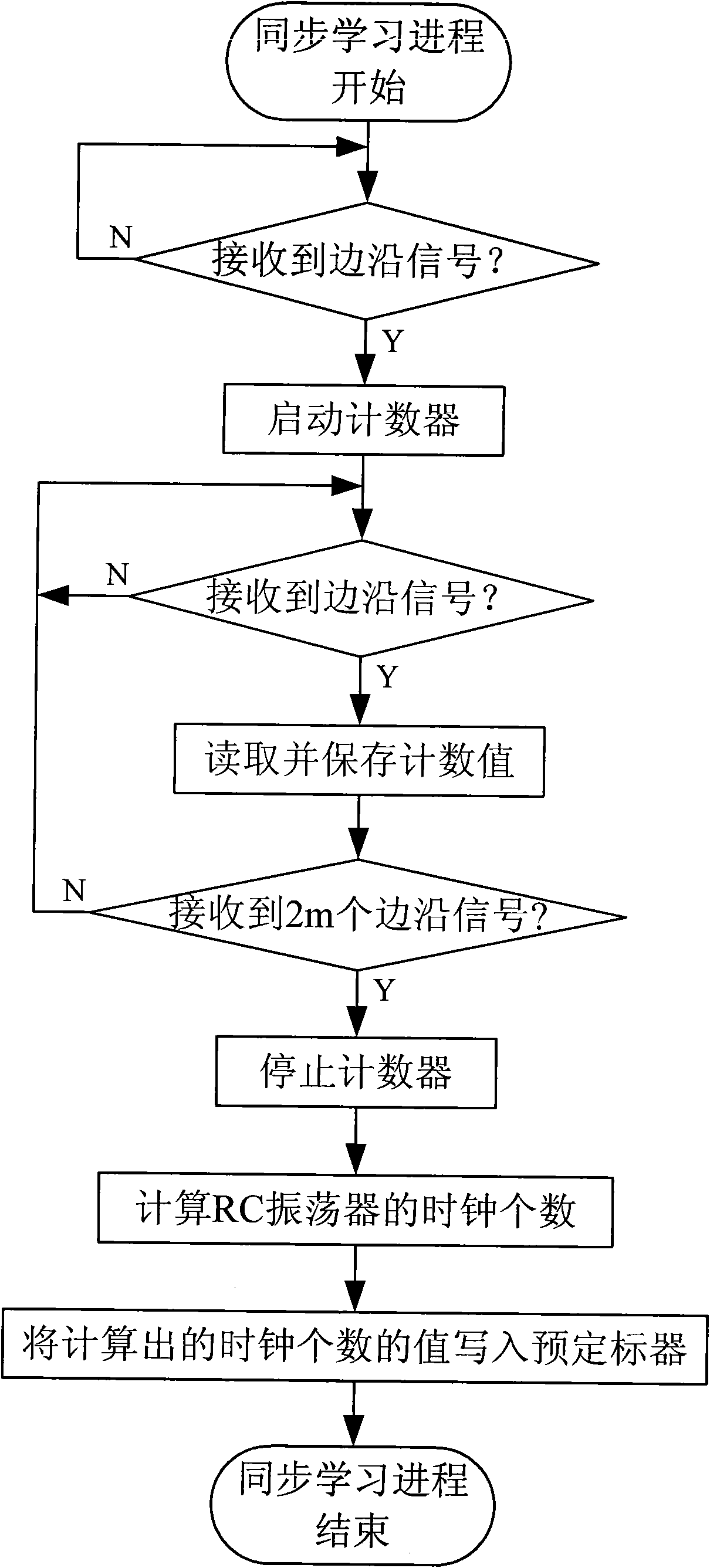
The invention provides an adjustable electronic detonator control chip. A clock circuit of the chip is a RC oscillator; and a logic control circuit comprises a programmable delay module, an input / output interface, a serial communication interface, a prescaler, a central processor, and a counter. One end of the counter is connected with the power output end of a power management circuit; one end isearthed; one end is connected with the central processor through an internal bus; and the other end and the central processor, the programmable extension module and the prescaler are connected and are connected with the RC oscillator together. The invention also provides a chip controlling flow which comprises a plurality of implementing proposals including a synchronous learning course, a clockadjusting course, a state re-reading course, a writing delay time course, an ignition course and other sub-flows. The technical proposal realizes the electronic detonator control chip with good shockresistance and integratability and enough time delay precision, thereby realizing an electronic detonator with high time delay precision.

Description

technical field [0001] The invention relates to the technical field of pyrotechnics manufacturing, in particular to a calibrated electronic detonator control chip and its control process, which are both shock-resistant, integrable, and high-delay precision. Background technique [0002] In the 1980s, Japan, Australia, Europe and other developed countries began to study electronic detonator technology. With the rapid development of electronic technology, microelectronic technology and information technology, electronic detonator technology has made great progress. In the late 1990s, electronic detonators began to be put into application testing and marketing. [0003] As the core component of the electronic detonator, the performance of the electronic detonator control chip directly affects the performance of the electronic detonator. The electronic detonator control chip given in the patent application documents 200820111269.7 or 200820111270.X and the patent ZL03156912.9 ...

Claims


Application Information

Patent Timeline
IPC IPC(8): F42C19/12
Inventor 颜景龙刘星李风国赖华平张宪玉
Owner 南通炜天电子科技有限公司
Learn More