
Hydraulic transduction device for wind power generation

An energy-converting device and hydraulic technology, which is applied in the directions of wind energy power generation, wind turbines, wind turbine combinations, etc., can solve the problems of large weight, waste, and high center of gravity of wind turbines, so as to save manufacturing costs and installation costs, increase Installation cost, overall weight reduction effect

Inactive Publication Date: 2009-11-25
XI AN JIAOTONG UNIV
View PDF0 Cites 8 Cited by
  • Summary
  • Abstract
  • Description
  • Claims
  • Application Information

AI Technical Summary

Problems solved by technology

[0005] (2) The speed of the generator is unstable: since the speed increaser is a speed change mechanism with a fixed speed ratio, the speed increaser will amplify the influence of the pulsating wind speed on the speed of the generator, resulting in the constant speed of the generator. Changes that affect the quality of power generation
[0006] (3) The center of gravity of the wind power generation device is too high: the weight of the speed increaser in the wind power generation device is large, which directly affects the operation stability of the wind power generation device. Therefore, the size and weight of the tower of the existing wind power generation device are directly increased, resulting in unnecessary waste
[0007] Difficulties in installation and maintenance of existing wind power generation devices: in existing wind power generation devices, the generator and speed-increasing mechanism are installed on the top of the tower, and a large tower crane is required for installation, which greatly increases the installation of existing wind power generation devices. Cost; during maintenance and repair, maintenance personnel have to go to the top of the tower for repair and maintenance work, which increases the maintenance and repair cost of the existing wind power generation device

Method used


Image

  • Hydraulic transduction device for wind power generation

Examples


Embodiment Construction

[0018] The present invention is described in further detail below in conjunction with accompanying drawing:

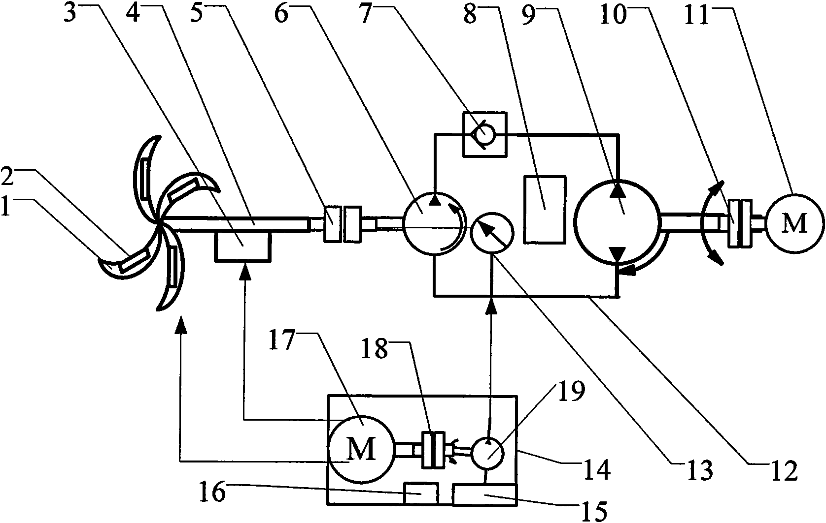
[0019] see figure 1 , a hydraulic transducer for wind power generation, the hydraulic transducer includes a first coupling 5, a hydraulic pump 6, a one-way valve 7, a hydraulic pressure protection device 13, a hydraulic motor 9 and a second coupling 18 The front end of the hydraulic pump 6 is connected to the wind-driven rotating main shaft 4 through the first coupling 5; the right end of the hydraulic pump 6 is connected to the right end of the hydraulic motor 9 through a hydraulic oil inlet pipeline; the left end of the hydraulic pump 6 and the left end of the hydraulic motor 9 are discharged through hydraulic pressure The pipeline is connected; the hydraulic oil inlet pipeline is provided with a check valve 7; the hydraulic oil in the hydraulic pump 6 enters the hydraulic motor 9 through the hydraulic oil outlet pipeline, and the hydraulic oil in the hydraulic motor...


PUM


Abstract

The invention discloses a hydraulic transduction device for wind power generation. The front end of a hydraulic pump is connected with a wind-power rotating main shaft through a first coupling; the back end of a hydraulic motor is connected with a first generator through a second coupling; the hydraulic pump converts pulse-type kinetic energy generated by the wind-power rotating main shaft into hydraulic energy; the hydraulic energy is transmitted to the hydraulic motor through a hydraulic oil outlet pipeline; the hydraulic motor converts the hydraulic energy into constant kinetic energy output to the first generator; a hydraulic pressure protection device is connected with the hydraulic oil outlet pipeline and maintains the pressure constancy of hydraulic oil in the hydraulic oil outlet pipeline; and a hydraulic auxiliary unit is arranged on the hydraulic transduction device. The invention reduces the overall weight of wind power generation devices, greatly saves metal materials and investment in wind power generation equipment, and provides a transduction device which is more convenient, effective and friendly to environment.

Description

Technical field: [0001] The invention belongs to the field of wind power generation, and relates to a core technology of wind power generation, in particular to a hydraulic secondary conversion and speed regulation power generation technology. Background technique: [0002] At present, the existing wind power generation device is generally composed of components such as a wind wheel, a generator, a speed increaser, a steering device (tail), a tower, a speed limiting safety mechanism, and an energy storage device. Since the wind speed in nature is extremely unstable, the output power of wind turbines is also extremely unstable. Generally, the electric energy generated by wind turbines cannot be directly used on electrical appliances or transmitted to the power grid. The speed is constant and the investment in wind power generation equipment is reduced. Although pitch adjustment technology for wind turbines, AC excitation variable speed constant frequency double-fed generator ...

Claims


Application Information

Patent Timeline
IPC IPC(8): F03D9/00F03D9/28
CPCF16H39/02Y02E10/72Y02P80/10
Inventor 要义勇李大海赵丽萍李天石
Owner XI AN JIAOTONG UNIV
Learn More