Corrugated plate for architectural shielding

A corrugated plate and corrugated formwork technology, which is used in buildings, building structures, covering/lining, etc., can solve problems such as difficulty in guaranteeing surface flatness, failure to solve leakage problems, and inability to meet test requirements, and achieve excellent surface quality. Shielding effectiveness, the effect of improving shielding effectiveness

Active Publication Date: 2010-07-07
常州新区金利达电子有限公司
View PDF0 Cites 0 Cited by
  • Summary
  • Abstract
  • Description
  • Claims
  • Application Information

AI Technical Summary

Problems solved by technology

Its disadvantages are as follows: complex process, high processing requirements, high cost, difficulty in ensuring surface smoothness, large installation work, many technical equipment, low efficiency, need for technicians to operate, and long construction period; secondly, due to the large shielding area, a single mold The size of the frame is limited by the processing equipment and process conditions, so it cannot be made into a large size. Therefore, the shielding joint is very long (thousands of meters to tens of thousands of meters), and there are shielding joints not only in the longitudinal direction, but also in the horizontal direction. The longer the seam, the greater the probability of leakage and the greater the impact on shielding effectiveness
[0004] Some non-professional units adopt the plan of lapping one half wave or two waves between the corrugated plates, but it does not solve the leakage problem of the seam, almost has no shielding effect, and cannot meet the test requirements

Method used


Image

  • Corrugated plate for architectural shielding
  • Corrugated plate for architectural shielding
  • Corrugated plate for architectural shielding

Examples


Embodiment 1

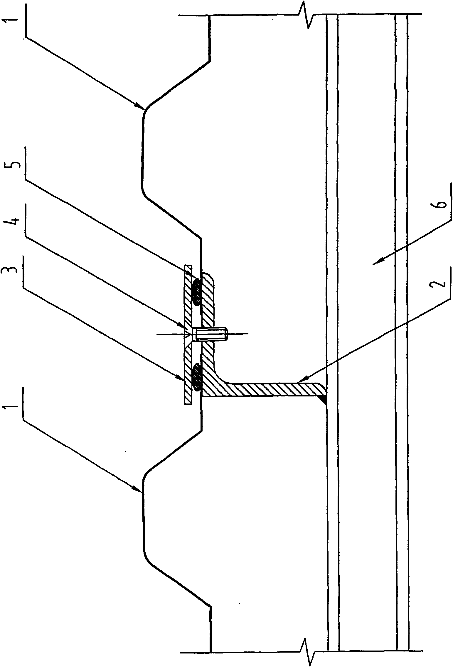
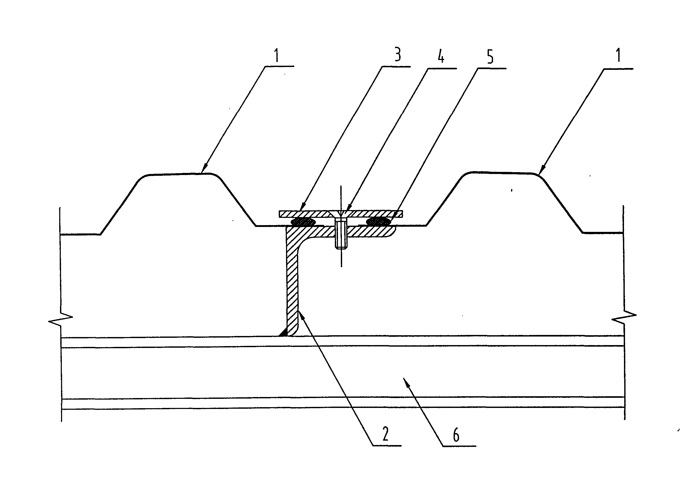
[0031] Such as figure 1 A corrugated plate used for building shielding includes corrugated templates 1 that are shielded and connected to each other, and the corrugated templates 1 are connected through a crimping structure, and adjacent corrugated templates 1 are electrically connected.

[0032] Below the joint of the corrugated formwork 1, there is an angle support connection 2 which is in contact with two adjacent corrugated formworks 1, and a crimping piece 3 is provided above the joint of two adjacent corrugated formworks 1, and the crimping piece 3 is connected to the corner. Type support 2 is connected by screw 4, and screw 4 can be countersunk screw.

[0033] A strip-shaped shielding gasket 5 is provided between the waveform template 1 and the crimping piece 3, which improves the shielding effectiveness of the gap and satisfies the shielding effectiveness of each frequency band.

[0034] The corner support connection 2 is welded and connected with the purlin 6 of the ...

Embodiment 2

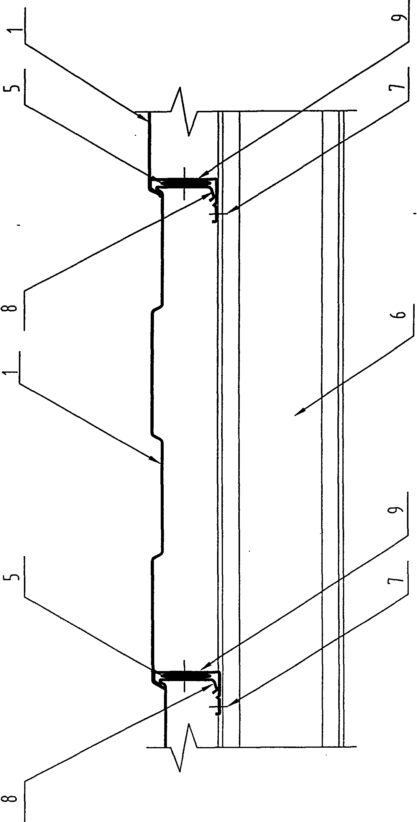
[0036] Such as figure 2 , a corrugated board for building shielding, comprising corrugated templates 1 that are shielded and connected to each other, the corrugated templates 1 are connected through a snap-fit ​​structure, and adjacent corrugated templates 1 are electrically connected.

[0037] One end of the waveform template 1 is provided with a clamping structure 8, and the other end is provided with a clamping groove 9. The waveform templates 1 are connected in turn, and the clamping structure 8 of each waveform template 1 is placed on another adjacent waveform template 1. in the clamping groove 9.

[0038] The clamping structure 8 and the clamping groove 9 are connected by resistance welding at the resistance welding point 7 .

[0039] A shielding gasket 5 is provided between the clamping structure 8 and the clamping groove 9, which improves the shielding effectiveness of the gap and satisfies the shielding effectiveness of each frequency band.

[0040] The corrugated ...


PUM


Abstract

A corrugated plate for architectural shielding and connection structure thereof, including waveshaped templates (1) shielding connected with each other, among the waveshaped templates (1) are connected by crimping structure or clamping structure, and the adjacent waveshaped templates (1) are electrically connected. In addition to conventional crimping, spiro union, riveting, welding and other programs, the invention provided seams shielding connection structure specifically utilizes resistance welding process, the seams are shielding connected by forcipated spot welding, the connection surfacehas small contact resistance, the surface has no damage and conquers defects of screw and riveting, both reducing shielding efficiency of seams caused by oxidation corrosion and conquering defects ofcontinuous welding, that are defects of large internal stress, surface irregularity and pollution in construction process. The process is provided with reliable connection, high efficiency, low costand good construction adaptability.

Description

technical field [0001] The invention relates to a shielding formwork, in particular to a corrugated plate suitable for large-scale factory building shielding (building shielding), especially for building shielding halls for electric test shielding. Background technique [0002] Domestic and foreign markets have a growing demand for large-scale plant shielding (building shielding), especially the power test shielding hall, and the market prospect is broad. [0003] At present, the shielding scheme of the high-voltage test hall is usually made of metal plates through multiple processes (cutting, punching, bending, welding, grinding, coating, etc.), and a single formwork (plate) is assembled and spliced ​​on site. Then install it on the wall of the building and the inside purlin on the top to form a shield. Its disadvantages are as follows: complex process, high processing requirements, high cost, difficulty in ensuring surface smoothness, large installation work, many technic...

Claims


Application Information

Patent Timeline
Patent Type & Authority Patents(China)
IPC IPC(8): E04F13/075E04F13/22
Inventor 李志珍李军
Owner 常州新区金利达电子有限公司
Why Eureka
Try Eureka