
Fingerprint image orientation enhancement method

A fingerprint image and fingerprint technology, applied in the field of fingerprint image orientation enhancement, can solve the problem of rough filtering effect, adaptability of fingerprint filtering enhancement technology, insufficient fingerprint enhancement effect, fracture of fingerprint image lines, or adhesion of fingerprint image lines with wet fingers, etc. question

Active Publication Date: 2012-10-17
HANGZHOU SYNOCHIP DATA SECURITY TECH CO LTD
View PDF2 Cites 1 Cited by
  • Summary
  • Abstract
  • Description
  • Claims
  • Application Information

AI Technical Summary

Problems solved by technology

[0005] However, the existing method of using Gabor filtering for fingerprints still has problems in the technical effect of direction enhancement, mainly in that the existing fingerprint image preprocessing only uses one-time Gabor filtering, and the filtering effect is too rough; The setting of ξ (equal to the reciprocal of the filter Gaussian envelope space constant δ) is a fixed empirical value based on the assumption that the quality of the fingerprint image is in an ideal state
In practical applications, if you encounter a fingerprint image in a non-ideal state, for example, if your finger is too dry to break the pattern of the fingerprint image, or if your finger is too wet to make the pattern of the fingerprint image stick, you need to dynamically adjust the value of δ and change the value of the filter passband ξ In order to adapt to the filtering requirements of different fingerprint image quality characteristics, the existing fingerprint filter enhancement technology has obvious shortcomings in terms of adaptability and fingerprint enhancement effect.

Method used


Image

  • Fingerprint image orientation enhancement method
  • Fingerprint image orientation enhancement method
  • Fingerprint image orientation enhancement method

Examples


Embodiment Construction

[0061] The technical solution proposed by the present invention will be further described below in conjunction with the accompanying drawings.

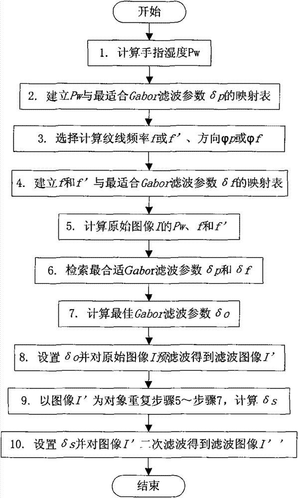
[0062] attached figure 1 It is a step-by-step implementation diagram of the technical solutions provided by the present invention. It is divided into 3 links and 10 steps. in:

[0063] 1) Link A includes steps 1 to 4, and its function is to establish various fingerprint images and the most suitable Gabor filter parameter δ p and δ f The corresponding relationship, and select the appropriate parameter calculation method according to the system resource configuration;

[0064] 2) Link B includes steps 5 to 8. Its function is to first analyze the digital features of the processed image, and then retrieve the most suitable filter parameters in the corresponding (mapping) relationship established in link A according to these digital features, and then Calculate the optimal filter parameter δ o , adjust the Gabor filtering parameter δ...


PUM


Abstract

The invention relates to the field of fingerprint image processing, in particular to a fingerprint image orientation enhancement method. The technical proposal adopted in the invention comprises the following steps of: 1) adding a step of Gabor pre-filtering, adjusting filtering parameters again after conducting preliminary directional filtering enhancement on the original image, and conducting secondary accurate Gabor filtering; and 2) adopting a self-adaptive measure of a Gabor filter transmission band to calculate respective numerical characteristics of the original fingerprint image and the pre-filtered fingerprint image and dynamically adjust the width of the filter transmission band. The fingerprint image orientation enhancement method has the beneficial effects: 1) the method improves the defects of the prior art that filtering is only implemented for once, the filtering parameter is an fixed experience value, and the filtering effect is too rough; 2) fingerprint ridges obviously separate, the edges of the ridges are smooth, the noise points are removed from the fingerprint ridges, and the original features such as scar and the like are kept simultaneously; and 3) compared with the prior art, the uniformity and definition of the fingerprint ridges, the capability of recovering the broken ridges and the like are remarkably improved.

Description

technical field [0001] The invention relates to the field of fingerprint image processing; in particular, it relates to a fingerprint image direction enhancement method. Background technique [0002] Fingerprints are made up of alternating ridges and valleys. In an ideal fingerprint image, the ridges and valleys are uniform in thickness. Except for individual areas such as minutiae and singular points, the ridges and valleys in most areas are parallel to each other and evenly spaced, presenting a continuous curve with a gentle change in direction. . When the fingerprint image is taken, due to various reasons, the fingerprint image cannot reach the above ideal state. It is necessary to use fingerprint image enhancement technology to eliminate noise, enhance the effective information in the original collected fingerprint image, and restore the real and clear fingerprint. The ridge structure achieves the effect of improving image quality. [0003] In digital image processing...

Claims


Application Information

Patent Timeline
Patent Type & Authority Patents(China)
IPC IPC(8): G06T5/00G06T5/20G06K9/00G06K9/46G06K9/52
Inventor 刘屹汪涤
Owner HANGZHOU SYNOCHIP DATA SECURITY TECH CO LTD
Learn More