Automatic synthesizing method of combinational logic circuit based on graph code
A combined logic circuit and automatic synthesis technology, applied in image coding, image data processing, instruments, etc.
- Summary
- Abstract
- Description
- Claims
- Application Information
AI Technical Summary
Problems solved by technology
Method used
Image
Examples
Embodiment 1
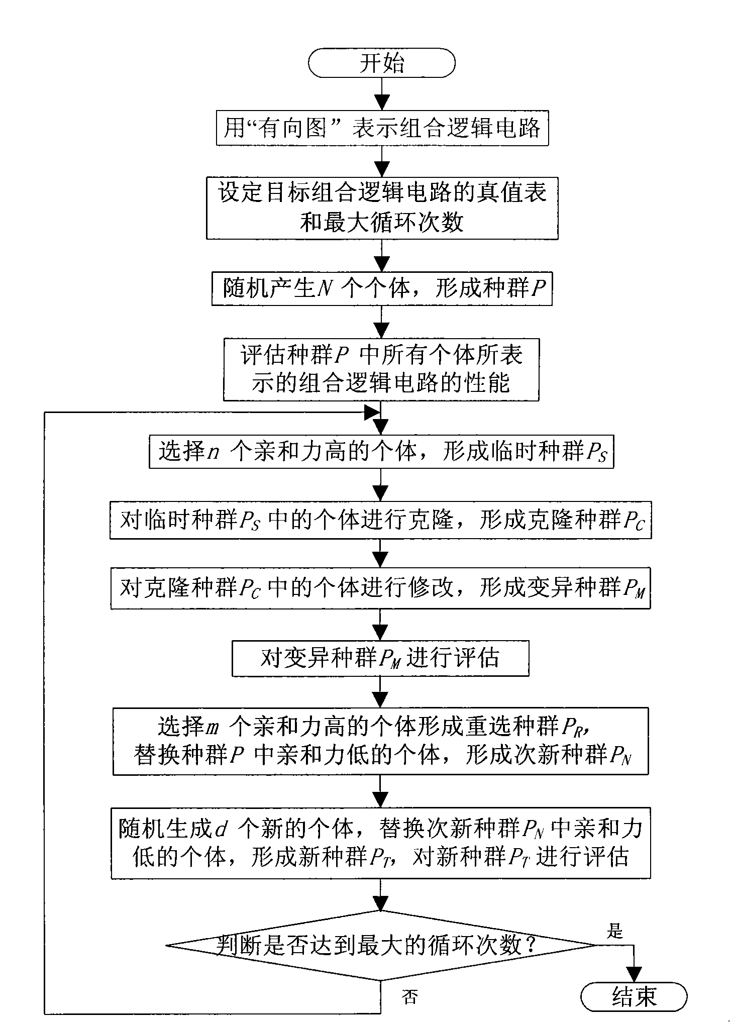
[0083] Embodiment 1 An automatic synthesis method of a three-input-output combinational logic circuit based on "graph" coding, the automatic synthesis step flow of the combinational logic circuit is as follows figure 1 Shown:
[0084] The first step: use "directed graph" ("graph" for short) to represent the combinational logic circuit, "graph" G is recorded as (V, E), V is the set of vertices of "graph", E is the edge of "graph" collection. in:
[0085] The vertices of the "graph" are divided into input vertices, output vertices and intermediate vertices, and the input vertices, output vertices and intermediate vertices are respectively represented by V IN , V OUT and V MID express. During evolution, V MID Allow addition, deletion or modification; V IN , V OUT Additions, deletions or modifications are prohibited; V’ IN , V' OUT Represent the input and output terminals of the combinational logic circuit, V' MID Represents different types of logic gates in combinati...
Embodiment 2
[0137] Embodiment 2 An automatic synthesis method of a four-input-output combinational logic circuit based on "graph" coding, the automatic synthesis step flow of the combinational logic circuit is as follows figure 1 Shown:
[0138] The first step: the same as the first step in embodiment 1.
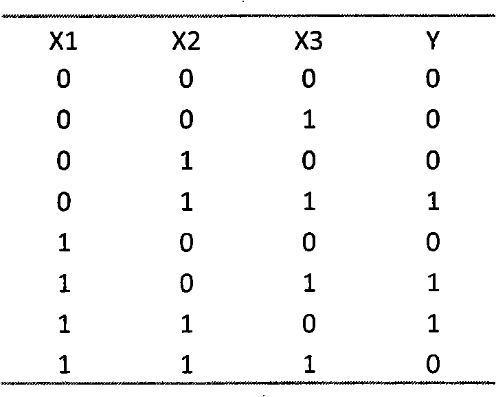
[0139] Step 2: Set as Image 6 The truth table of the target combinatorial logic circuit shown and the maximum number of cycles is 100.
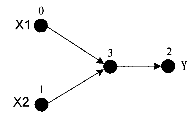
[0140] Step 3: template combinatorial logic circuit such as image 3 As shown, it is a combinational logic unit composed of a logic gate with two inputs and one output, two input terminals and one output terminal; any individual in the population is a "graph" coding form of a combinational logic circuit, and the individual is combined in the template The logic circuit is based on random generation. The process of individual generation is: randomly adding new vertices to the template combinational logic circuit, the number and position of the new ...
Embodiment 3
[0173] Embodiment 3 An automatic synthesis method of a four-input and three-output combinational logic circuit based on "graph" coding, the automatic synthesis step flow of the combinational logic circuit is as follows figure 1 Shown:
[0174] The first step: the same as the first step in embodiment 1.
[0175] Step 2: Set as Figure 9 The truth table of the target combinational logic circuit and the maximum number of cycles shown is 500.
[0176] Step 3: template combinatorial logic circuit such as image 3 As shown, it is a combinational logic unit composed of a logic gate with two inputs and one output, two input terminals and one output terminal; any individual in the population is a "graph" coding form of a combinational logic circuit, and the individual is combined in the template The logic circuit is based on random generation. The process of individual generation is: randomly adding new vertices to the template combinational logic circuit, the number and position ...
PUM
 Abstract
Description
Claims
Application Information
 - Generate Ideas
- Intellectual Property
- Life Sciences
- Materials
- Tech Scout
- Unparalleled Data Quality
- Higher Quality Content
- 60% Fewer Hallucinations
Browse by: Latest US Patents, China's latest patents, Technical Efficacy Thesaurus, Application Domain, Technology Topic, Popular Technical Reports.
© 2025 PatSnap. All rights reserved.Legal|Privacy policy|Modern Slavery Act Transparency Statement|Sitemap|About US| Contact US: help@patsnap.com


