
Lithology while drilling and reservoir characteristics recognizing method

An identification method and lithology technology, applied in the field of logging while drilling and measurement, can solve problems such as weak vibration characteristics and increased difficulty in analysis and judgment

Inactive Publication Date: 2009-11-11
ZHIXIN COMM SCI & TECH SHANGHAI
View PDF0 Cites 34 Cited by
  • Summary
  • Abstract
  • Description
  • Claims
  • Application Information

AI Technical Summary

Problems solved by technology

When using a PDC bit, because it has no cone and small teeth, the vibration characteristics reflected to the ground are weaker than that of the cone bit, which increases the difficulty of analysis and judgment

Method used


Image

  • Lithology while drilling and reservoir characteristics recognizing method
  • Lithology while drilling and reservoir characteristics recognizing method
  • Lithology while drilling and reservoir characteristics recognizing method

Examples


Embodiment Construction

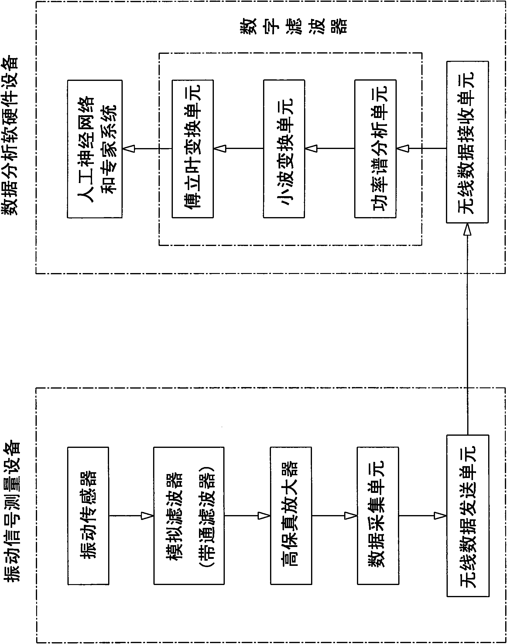
[0038] Please refer to figure 1 , the present invention is a method for identifying lithology and reservoir characteristics while drilling, comprising the following steps:

[0039] Step 1. Establish data analysis software and hardware equipment on the ground. The data analysis software and hardware equipment is composed of digital filter, wireless data receiving unit, artificial neural network and expert system; digital filter is composed of three stages, the first stage is power spectrum The analysis unit, the second stage is a wavelet transform unit, and the third stage is a Fourier transform unit.

[0040]Step 2. Install the vibration signal measuring equipment, which is installed on the top of the drill string at the oil wellhead or in the downhole measuring device. The vibration signal measuring equipment consists of a vibration sensor, an analog filter, a high-fidelity amplifier, and a data acquisition unit Composed of a wireless data sending unit, the vibration sensor ...


PUM


Abstract

A lithology while drilling and reservoir characteristics recognizing method comprises the following steps: (1), establishing data analysis software and hardware equipment; (2), mounting vibration signal measuring equipment; (3), transmitting vibration acoustic wave signals by a vibration transducer to an analog filter; (4), filtering useless frequency bands in the signals and transmitting useful frequency bands to a high fidelity amplifier by the analog filter; (5), amplifying, strengthening, and transmitting the signals to a digital filter by the high fidelity amplifier; (6), transmitting power spectral density of the signals to a wavelet transformation unit by a power spectrum analysis unit, (7), performing wavelet decomposition, reconstruction and noise elimination on the signals by the wavelet transformation unit; and (8), unfolding restored true signals in spectrographs and energy spectrum charts by a Fourier transformation unit, and determining multiple kinds of lithology and reservoir fluid characteristics by recognizing each group of spectrum lines. The method detects and filters the vibration acoustic wave signals, extracts stratum information, and obtains the lithology and the reservoir fluid characteristics through noise elimination and spectral analysis.

Description

technical field [0001] The invention relates to drilling-while-drilling mud logging and measurement technology in the oil drilling process, in particular to drilling tool stress wave detection and analysis technology. Background technique [0002] In conventional geological mud logging, geological stratification, horizon identification and cuttings description are mainly carried out based on drilling time, cuttings samples and gas measurement values. However, for the lithology of thin layers and interlayers that appear in the formation, we often cannot accurately describe them in the case of non-intensified sampling intervals or coring, and the loss of blocks in sand samples and the experience of geologists will result in the description of cuttings The distortion of the cuttings reduces the coincidence rate of the section described by the cuttings. With the extensive use of PDC bits, the drilling speed has been greatly increased. However, because the working principle of P...

Claims


Application Information

Patent Timeline
IPC IPC(8): E21B49/00
Inventor 高岩
Owner ZHIXIN COMM SCI & TECH SHANGHAI
Learn More