
Torque transmission unit

A technology of torque transmission and rotation axis, which is applied in the directions of wing leaf parts, hinge plates, transportation and packaging, etc. It can solve the problems of large structural size and weight, exceeding the expected value, and achieve the effect of saving space

Inactive Publication Date: 2014-03-19
MAGNA POWERTRAIN AG & CO KG
View PDF6 Cites 0 Cited by
  • Summary
  • Abstract
  • Description
  • Claims
  • Application Information

AI Technical Summary

Problems solved by technology

However, depending on the practical application or the required clutch torque, the torque transfer unit - and in particular the magneto-rheological clutch - is too large in size and weight to be expected

Method used


Image

  • Torque transmission unit
  • Torque transmission unit
  • Torque transmission unit

Examples


Embodiment Construction

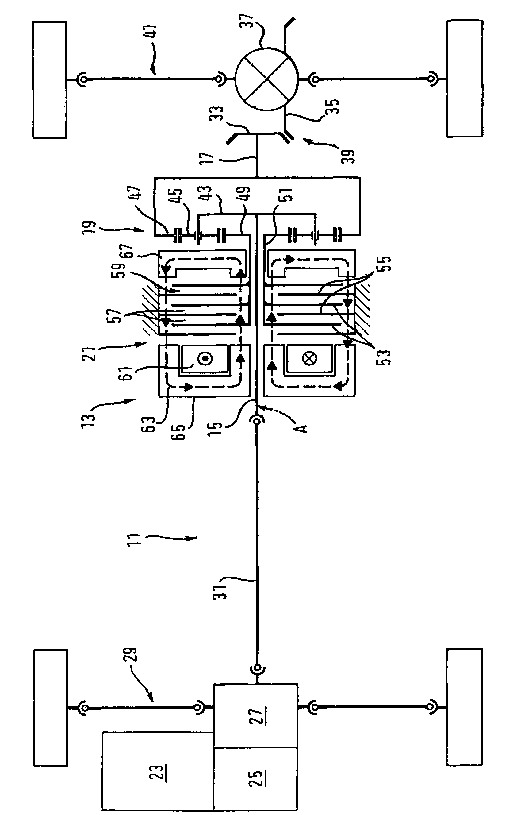
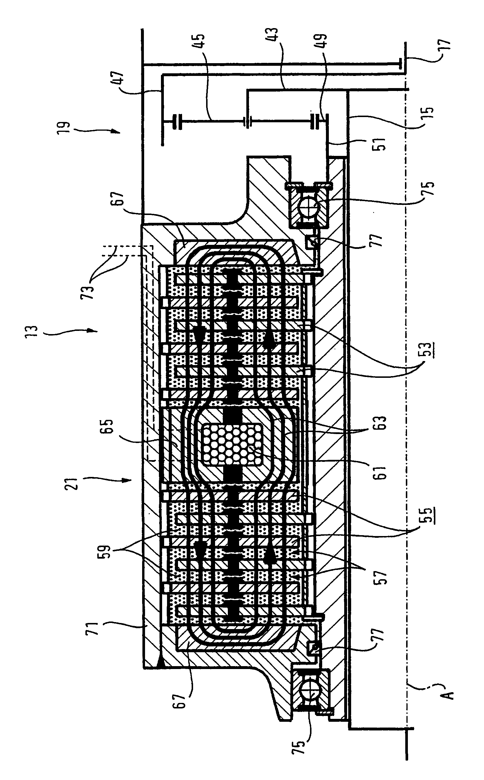
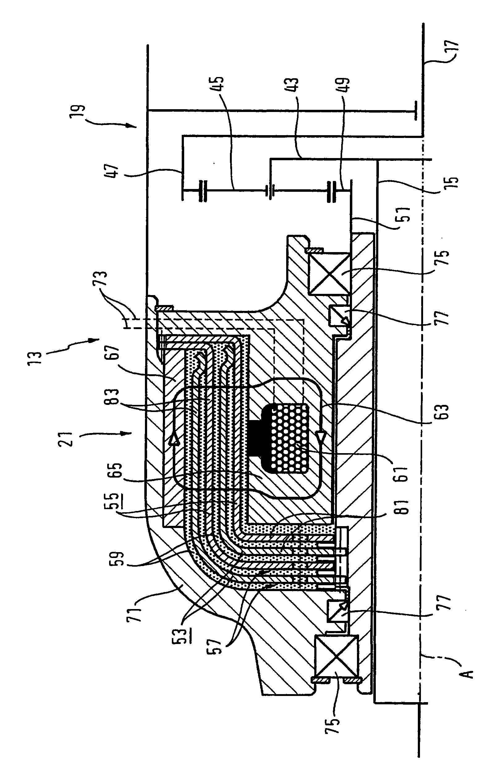
[0029] figure 1 A transmission arrangement is shown, which is configured as a torque transfer unit 13 in a drive train 11 of a motor vehicle with switchable all-wheel drive. The torque transfer unit 13 has: a drive shaft 15; a driven shaft 17; a planetary gear 19 coupled to the drive shaft 15 and the driven shaft 17; and a magneto-rheological clutch 21 coupled to the planetary gear 19, the clutch is This configuration is a brake.

[0030] The drive train 11 of the motor vehicle also comprises: a drive unit 23 , such as an internal combustion engine; a transmission 25 coupled thereto (manually or automatically controlled); and a transfer case 27 . This transfer case 27 transmits the drive torque via a front axle differential not shown to the wheels of a front axle 29 which, in the exemplary embodiment shown, forms the continuously driven vehicle axle and is therefore called spindle. In addition, the transfer case 27 transfers part of the transmission torque via the cardan shaf...


PUM


Abstract

The invention relates to a torque transmission unit for a motor vehicle with a permanently driven primary axle and a switchable secondary axle, comprising a first connecting part and a second connecting part. The invention furthermore comprises several lamellas that are divided into primary lamellas and secondary lamellas in an alternating arrangement. The unit further comprises a planetary gear system, comprising an at least first gear element, rotationally connected with the first connection part, a second gear element, rotationally connected with the second connection part, and a third gear element, rotationally connected with the primary lamellas. The secondary lamellas are rotationally connected with the first connection part, the second connection part or with a stationary housing part. The torque transmission unit further comprises at least one electric coil for producing a magnetic field, acting on a magnetorheoplogical medium, wherein each primary lamella and secondary lamella is surrounded at least on two sides by the magnetorheological medium. The planetary gear system induces a torque of the primary lamellas into acceleration with a turning movement of the second connecting part in relation to the first connecting part.

Description

technical field [0001] The invention relates to a torque transmission unit for a motor vehicle with a continuously driven main shaft and a switchable auxiliary shaft. Such a torque transmission unit has a first connecting part and a second connecting part, which are rotatable relative to each other, wherein the first connecting part is provided for direct or indirect connection with a drive unit of a motor vehicle and the second connecting part It is provided for direct or indirect connection with the layshaft of the motor vehicle, or vice versa. The torque transfer unit is thus used to transfer part of the drive torque to the layshaft. The first connecting part and the second connecting part may be a driving shaft and a driven shaft, or vice versa. In particular, such a torque transfer unit can be part of a transfer case with an integrated offset drive, that is to say with an input shaft and two output shafts. Background technique [0002] Such torque transfer units can ...

Claims


Application Information

Patent Timeline
Patent Type & Authority Patents(China)
IPC IPC(8): B60K17/35
CPCE05Y2201/72E05Y2201/21F16D2037/007F16D57/002E05Y2400/21E05D11/082F16D2037/004F16D37/02E05Y2201/266E05Y2201/254E05Y2900/531E05Y2201/25E05F5/00
Inventor 赫伯特·施泰因文德弗朗茨·格拉策杰拉尔德·朔贝尔
Owner MAGNA POWERTRAIN AG & CO KG
Learn More