Method for manufacturing intelligent composite-material laminates used for monitoring structural longitudinal strain

A composite material layer and manufacturing method technology, applied in measurement devices, optical devices, instruments, etc., can solve the problems affecting the grating strain measurement accuracy, the process cannot be guaranteed, and the optical fiber is easily damaged, so as to improve the strain monitoring accuracy and avoid chirps. Chirp phenomenon, the effect that meets the sensitivity requirements

Inactive Publication Date: 2009-11-04
SHENYANG INST OF AERONAUTICAL ENG +1
View PDF1 Cites 30 Cited by
  • Summary
  • Abstract
  • Description
  • Claims
  • Application Information

AI Technical Summary

Problems solved by technology

[0003] In engineering, polyimide resin or epoxy resin is usually used to bond the fiber grating sensor to the surface of the structure, but the fiber is particularly easy to damage during service
Therefore, sometimes the optical fiber is directly embedded in the composite material structure for strain and temperature monitoring. At the same time, the composite material can also play a good role in packaging and protecting the optical fiber, but the embedding of the fiber grating will cause the concentration of stress/strain around it, and at the same time The thermal residual stre

Method used


Image

  • Method for manufacturing intelligent composite-material laminates used for monitoring structural longitudinal strain
  • Method for manufacturing intelligent composite-material laminates used for monitoring structural longitudinal strain
  • Method for manufacturing intelligent composite-material laminates used for monitoring structural longitudinal strain

Examples


Embodiment Construction

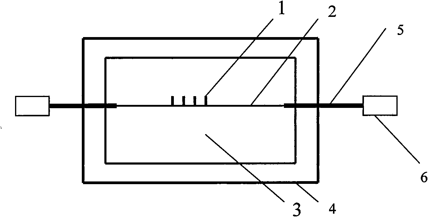
[0016] see figure 1 , a method for manufacturing an intelligent composite laminate for structural longitudinal strain monitoring, the steps are as follows:

[0017] (1) Choose a CFRP with a thickness of 0.2mm or a GFRP composite prepreg with a thickness of 0.15mm. CFRP is laminated according to the warp / weft direction of 50 / 50 (mass ratio); GFRP is laid according to the warp / weft direction of 80 / 20 (mass ratio) ) of the lay-up structure lay-up;

[0018] (2) The composite material prepreg is cut according to 100mm×20mm, and the layers are laid by hand;

[0019] (3) Apply prestress at both ends of the fiber grating to be embedded, put it into the composite material laminate along the 100mm direction, and embed the port part into the composite material with a quartz protective sleeve;

[0020] (4) Seal the composite material layer with a vacuum bag, and the fiber grating passes through the vacuum bag through the silicone rubber sealing strip;

[0021] (5) Put the composite lay...


PUM


Abstract

The invention provides a method for manufacturing intelligent composite-material laminates used for monitoring structural longitudinal strain. In order to solve the technical problems that as fiber grating sensors are bonded to the surface of a structure through polyimide resin or epoxy resin commonly used in the prior engineering, optic fiber in service is easily destroyed; the optic fiber can get encapsulation protection but cause the concentration of surrounding stress/strain thereof if the optic fiber is directly embedded in a composite-material structure; and thermal residual stress produced in a material-curing process can cause chirp phenomena of fiber grating reflection spectrum to affect the measurement accuracy of grating strain, and the like, the invention provides the method for manufacturing intelligent composite-material laminates used for monitoring structural longitudinal strain. In the method, the fiber grating sensors are embedded in composite-material layers to replace resistance strain gauges commonly used in the field of monitoring structural health; by applying prestress to embedded fiber gratings, the influence of the curing residual stress of composite material on the fiber grating reflection spectrum is reduced so as to avoid the chirp phenomena; and the stability and repeatability of the sensors are improved. In addition, the composite material plays a good role in encapsulating and protecting bare fiber gratings, and meets engineering construction requirement on sensor sensitivity.

Description

Technical field: [0001] The invention belongs to a method for preparing an intelligent composite material, in particular to a method for preparing an intelligent composite material laminate embedded in an optical fiber grating sensor for structural longitudinal strain detection. Background technique: [0002] In recent years, fiber grating sensors have been widely used in the field of longitudinal strain monitoring of engineering structures. Compared with traditional strain gauges, fiber gratings have the function of wavelength division multiplexing, and multiple points of the structure can be detected simultaneously by using one optical fiber. In addition, the optical fiber is not subject to electromagnetic interference, does not need insulation protection with structural materials, and is resistant to high temperatures. , Anti-chemical corrosion, can be used as an ideal method for detecting longitudinal strain monitoring in concealed environments and inaccessible areas. ...

Claims


Application Information

Patent Timeline
IPC IPC(8): B29C70/34B29C70/54G01B11/16B29L9/00
Inventor 卢少微陈平马克明王柏臣陆春李伟于祺
Owner SHENYANG INST OF AERONAUTICAL ENG
Why Eureka
Try Eureka