Tool holder for a rotating tool and method for clamping a rotating tool in tool holder

A technology for rotating tools and tool holders, which is applied in the field of tool holders and for clamping rotating tools in tool holders, and can solve problems such as limiting the feed speed of machine tools

Inactive Publication Date: 2009-11-04
FRANZ HAIMER MASCHINENBAU KG
View PDF1 Cites 5 Cited by
  • Summary
  • Abstract
  • Description
  • Claims
  • Application Information

AI Technical Summary

Problems solved by technology

This limits the achievable feed rate of the machine tool

Method used


Image

  • Tool holder for a rotating tool and method for clamping a rotating tool in tool holder
  • Tool holder for a rotating tool and method for clamping a rotating tool in tool holder
  • Tool holder for a rotating tool and method for clamping a rotating tool in tool holder

Examples


Embodiment Construction

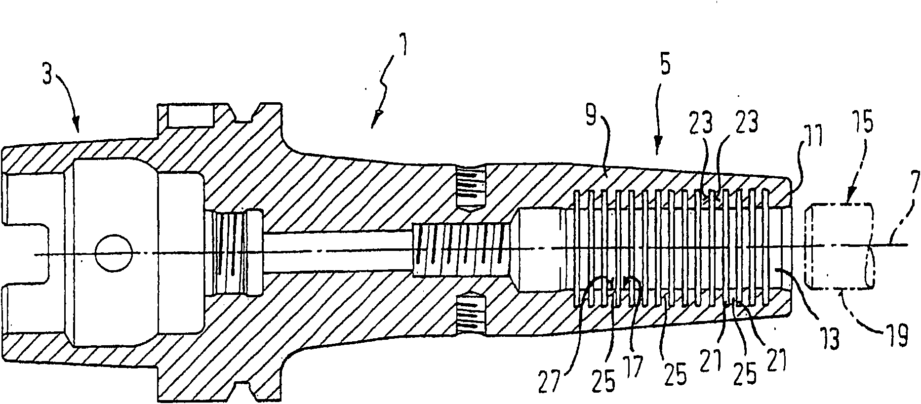
[0042] figure 1 A tool holder 1 of the shrink chuck type is shown, comprising an engagement portion 3, here in the form of a hollow shank taper (HSK), for rotationally fixed engagement with a working spindle of a machine tool at its axial end ; and a clamping portion 5 at the other axial end thereof. The axis of rotation of the tool holder 1 is indicated with 7 . The engagement portion 3 can have any shape, ie also in the form of a steep taper or the like. The clamping part 5 has the basic shape of a housing 9 , which terminates in an end face 11 extending perpendicular to the axis of rotation 7 and comprises a cylindrical receiving opening 13 concentric to the axis of rotation 7 , a rotary tool not shown in detail, A cylindrical tool shank 15 , for example a milling cutter or a drilling tool, is inserted exchangeably into the receiving bore as will be described in more detail later. for clarity figure 1 The tool shank 15 is shown prior to insertion into the receiving hole...


PUM


Abstract

The present invention relates to a tool holder (1), the housing section (5) of which comprises clamping means (9), provided concentrically with a rotational axis (7) of the tool holder (1) and defining a housing opening (13). The clamping means (9) can be radially adjusted between a release position and a clamping position, in which the clamping means (9) exert a radial compression seating force on a hilt (15) in the clamping position. The clamping means (9) are provided with a clamping surface (17), which makes a surface contact with the outer circumferential surface (19) of the hilt (15) in the clamping position. The region of the tool holder (1) forming the clamping surface (17) comprises a plurality of groove parts, which, viewed in the direction of the rotational axis, are connected in one piece, forming support regions at an axial separation from each other, projecting towards the rotational axis (7), the peak surfaces (27) of which, facing the rotational axis, form the cylindrical clamping surface.

Description

[0001] This application is a divisional application of the invention patent application with application number 200580025089.6. The international filing date of the original application was June 14, 2005, and the title of the invention was "Tool Fixture for Rotary Tool". technical field [0002] The invention relates to a tool holder for a rotary tool and a method for clamping a rotary tool in the tool holder. Background technique [0003] In practice, various tool holders are used for clamping rotating tools, such as drills or milling cutters, whose clamping device fixes the tool holder of the rotating tool with a radial force fit with a slight maximum displacement. Relates to the rule that the smaller the clamping displacement, the higher the precision and concentricity of the tool holder. In this way, precision spring collets have a clamping displacement of only a few millimeters, while other precision collets, such as hydraulic expansion collets or mechanism collets wit...

Claims


Application Information

Patent Timeline
Patent Type & Authority Applications(China)
IPC IPC(8): B23Q3/00
Inventor 弗朗茨·海默
Owner FRANZ HAIMER MASCHINENBAU KG
Why Eureka
Try Eureka