
Hydraulic pressure control apparatus

A control equipment and hydraulic technology, which is applied in the direction of mechanical equipment, transmission device control, fluid pressure actuation device, etc., can solve the problems of reduced durability of torque converter, reduced engagement degree of lock-up clutch, etc., and achieve reduced durability minimal effect

Inactive Publication Date: 2013-03-27
TOYOTA JIDOSHA KK
View PDF1 Cites 0 Cited by
  • Summary
  • Abstract
  • Description
  • Claims
  • Application Information

AI Technical Summary

Problems solved by technology

As a result, the durability of the torque converter can decrease due to the increase in secondary pressure, or the degree of engagement of the lockup clutch can decrease due to the decrease in secondary pressure

Method used


Image

  • Hydraulic pressure control apparatus
  • Hydraulic pressure control apparatus
  • Hydraulic pressure control apparatus

Examples


Embodiment Construction

[0024] Exemplary embodiments of the present invention will be described below with reference to the accompanying drawings.

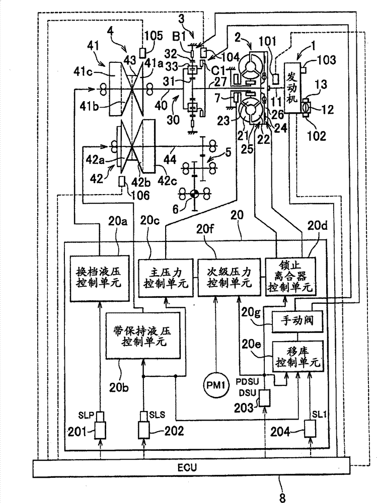
[0025] A first embodiment of the present invention will be described below. figure 1 is a view schematically showing the structure of the vehicle according to the first embodiment of the present invention.

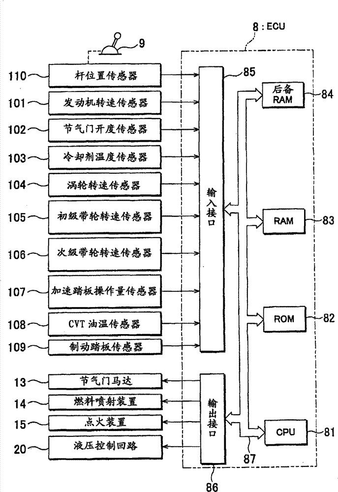
[0026] figure 1 The vehicle shown in is a front-engine front-wheel drive (FF) vehicle that includes an engine (internal combustion engine) 1 as a power source for driving the vehicle, a torque converter 2 as a fluid transfer unit, and a forward / reverse switching unit 3. A belt type continuously variable transmission (CVT) 4, a reduction gear unit 5, a differential gear unit 6 and an electronic control unit (ECU) 8 serving as a control unit.

[0027] A crankshaft 11 serving as an output shaft of the engine 1 is connected to the torque converter 2 . The output from the engine 1 is transmitted from the torque converter 2 to the differential gear unit...


PUM


Abstract

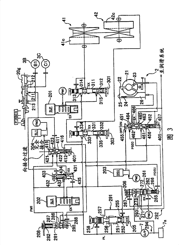
A hydraulic pressure control apparatus includes a primary regulator valve that regulates a pressure discharged from an oil pump to form a line pressure that is used as an original pressure for a hydraulic pressure that is supplied to each element, and a secondary regulator valve that regulates a hydraulic pressure downstream of the primary regulator valve to form a secondary pressure. Two pilot pressures (first modulator hydraulic pressure, control hydraulic pressure from a duty solenoid) are supplied to the secondary regulator valve. The secondary regulator valve is configured in such a manner that when one of the pilot pressures changes, a change in the one of the pilot pressures is absorbed by the other pilot pressure.

Description

technical field [0001] The invention relates to a hydraulic control device of a vehicle power transmission system. Background technique [0002] There is a hydraulic control apparatus of a vehicle power transmission system that includes a first regulating unit (primary regulating valve) and a second regulating unit (secondary regulating valve) (see, for example, Japanese Patent Application Publication No. 2007-78011 (JP-A -2007-78011)). The primary regulating valve regulates the hydraulic pressure (discharge pressure) generated by the oil pump to form a main pressure which is used as an initial pressure (control initial pressure) of the hydraulic pressure supplied to each element. The secondary regulator valve is disposed downstream of the primary regulator valve, and regulates hydraulic pressure discharged from the primary regulator valve to form a secondary pressure. The secondary pressure formed by the secondary regulating valve is applied to, for example, a control val...

Claims


Application Information

Patent Timeline
Patent Type & Authority Patents(China)
IPC IPC(8): F16H61/00F16H61/14
CPCF15B2211/634F16H61/143F15B2211/76F15B2211/6346F15B2211/50554F16H61/66272F15B2211/528F15B2211/6653F16H61/0206F16H61/0021F15B2211/6651F15B2211/57F15B2211/565F15B2211/6336F15B2211/633F15B2211/55F15B2211/324F15B2211/7052F15B2211/526F15B11/028F15B2211/6051F15B2211/6333F15B2211/71F16H2061/6608F15B2211/6343F15B2211/6355Y10T137/86002
Inventor 大形勇介青山俊洋
Owner TOYOTA JIDOSHA KK
Learn More