a clamping device

A technology of clamping device and set, which is applied in the direction of quenching device, heat treatment equipment, furnace, etc., can solve the problems of limited diameter range, inconvenient replacement of expansion sleeves, and processing constraints of workpieces with different diameters, so as to achieve the effect of ensuring the working life

Inactive Publication Date: 2011-12-14
北京宜飞航空科技有限公司
View PDF2 Cites 0 Cited by
  • Summary
  • Abstract
  • Description
  • Claims
  • Application Information

AI Technical Summary

Problems solved by technology

The diameter range of the clamping workpiece is very limited, and it is very inconvenient to replace the expansion sleeve; this greatly restricts the processing of workpieces with different diameters

Method used


Image

  • a clamping device
  • a clamping device
  • a clamping device

Examples


Embodiment Construction

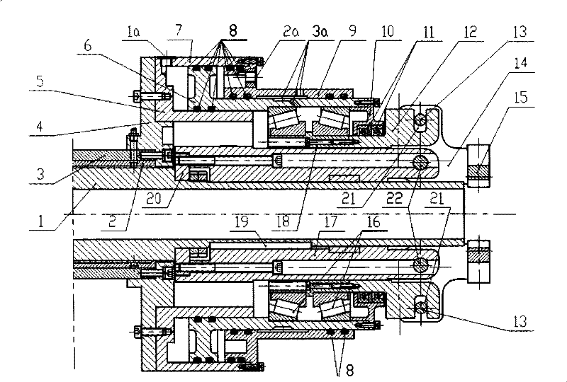
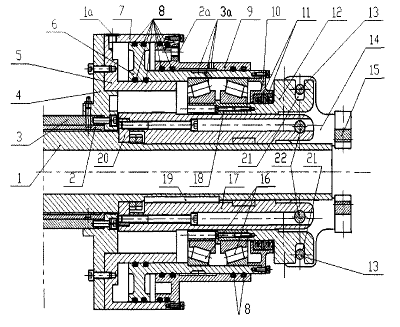
[0054] figure 1 is a cross-sectional view of a clamping device according to the invention. In the following description with figure 1 The right side is the front, and the left side is the back. As shown, the clamping device according to the invention comprises a hollow spindle 1 . During actual processing, the cooling medium—in this embodiment, cooling water—flows through the hollow part of the hollow spindle 1 into the interior of the quenched workpiece, thereby cooling the quenched workpiece from the inside.

[0055] The bearing sleeve 17 is arranged concentrically with the hollow spindle 1 . It can be seen from the figure that due to the needs of processing technology and installation, the supporting sleeve 17 and the sliding sleeve 12 are composed of multiple parts. But in this embodiment, for convenience of description, the combination of these parts is referred to as supporting sleeve 17 and sliding sleeve 12 according to their functions. The support sleeve 17 is ro...


PUM


Abstract

The invention relates to a clamping device, in particular to a clamping device for clamping a long tubular workpiece during quenching treatment. The device comprises a rotatably supported hollow main shaft; a support sleeve coaxially sleeved on the hollow main shaft and axially fixedly connected with it; a double-acting cylinder, which is rotatably supported relative to the support sleeve; a sliding sleeve, the inner surface of the sliding sleeve is slidably supported on the outer peripheral surface of the supporting sleeve; a crank plate, the crank plate is hingedly connected with the ends of the supporting sleeve and the sliding sleeve respectively; Jaws fixedly connected to the crank plate.

Description

technical field [0001] The invention relates to a clamping device, in particular to a clamping device for clamping a long tubular workpiece during quenching treatment. Background technique [0002] When processing long tubular workpieces, such as unpowered axles used on car trailers, drill pipes in oil field drilling and mining, etc., it is necessary to quench the workpiece. When quenching, it is usually necessary to clamp the workpiece to be processed with a certain force, and then carry out handling and processing of the workpiece. [0003] When heat-treating long tubes, such as quenching, the hot workpiece is usually placed vertically in a cooling pool. This requires clamping a section of the workpiece, which is then lifted and moved into the cooling bath. At this time, it is not only necessary to firmly clamp the workpiece, but also hope that the cooling medium can pass through the pipe fittings comfortably, so as to uniformly cool the inside and outside of the pipe fi...

Claims


Application Information

Patent Timeline
Patent Type & Authority Patents(China)
IPC IPC(8): C21D1/62C21D9/08
Inventor 高庆郭占江任剑波
Owner 北京宜飞航空科技有限公司
Why Eureka
Try Eureka