Dimming system of underwater lamp

An underwater lamp and dimming technology, which is applied in signal transmission systems, light sources, electric light sources, etc., can solve the problems of not being able to meet the needs of lighting at the same time, poor video effects, long transmission distance, etc., and achieve light weight and dimming Simple, simple interface effect

Inactive Publication Date: 2009-10-14
SHENYANG INST OF AUTOMATION - CHINESE ACAD OF SCI
View PDF0 Cites 8 Cited by
  • Summary
  • Abstract
  • Description
  • Claims
  • Application Information

AI Technical Summary

Problems solved by technology

The adjustment of the brightness of the underwater lights on the conventional underwater robot is realized by changing the voltage of the voltage-adjustable transformer on the water surface. The disadvantage of this method is that if the voltage is changed, all the lights on the underwater robot will be changed, which will lead to other adjustments. The change of the lighting of the good camera will cause the video effect of the observed target to be bad, and because the transmission distance from the water surface to the underwater robot carrier is very long, the resistance on the transmission path is very large, which consumes unnecessary power. Generally speaking, it is also a bottleneck for deep underwater robots
With the development of the marine industry, the missions to be completed are becoming more and more complex, and more underwater cameras are required for underwater robots. The traditional dimming method of underwater lights cannot meet the lighting requirements of multiple cameras on underwater robots at the same time.

Method used


Image

  • Dimming system of underwater lamp
  • Dimming system of underwater lamp
  • Dimming system of underwater lamp

Examples


Embodiment Construction

[0020] The present invention will be described in further detail below in conjunction with the accompanying drawings and embodiments.

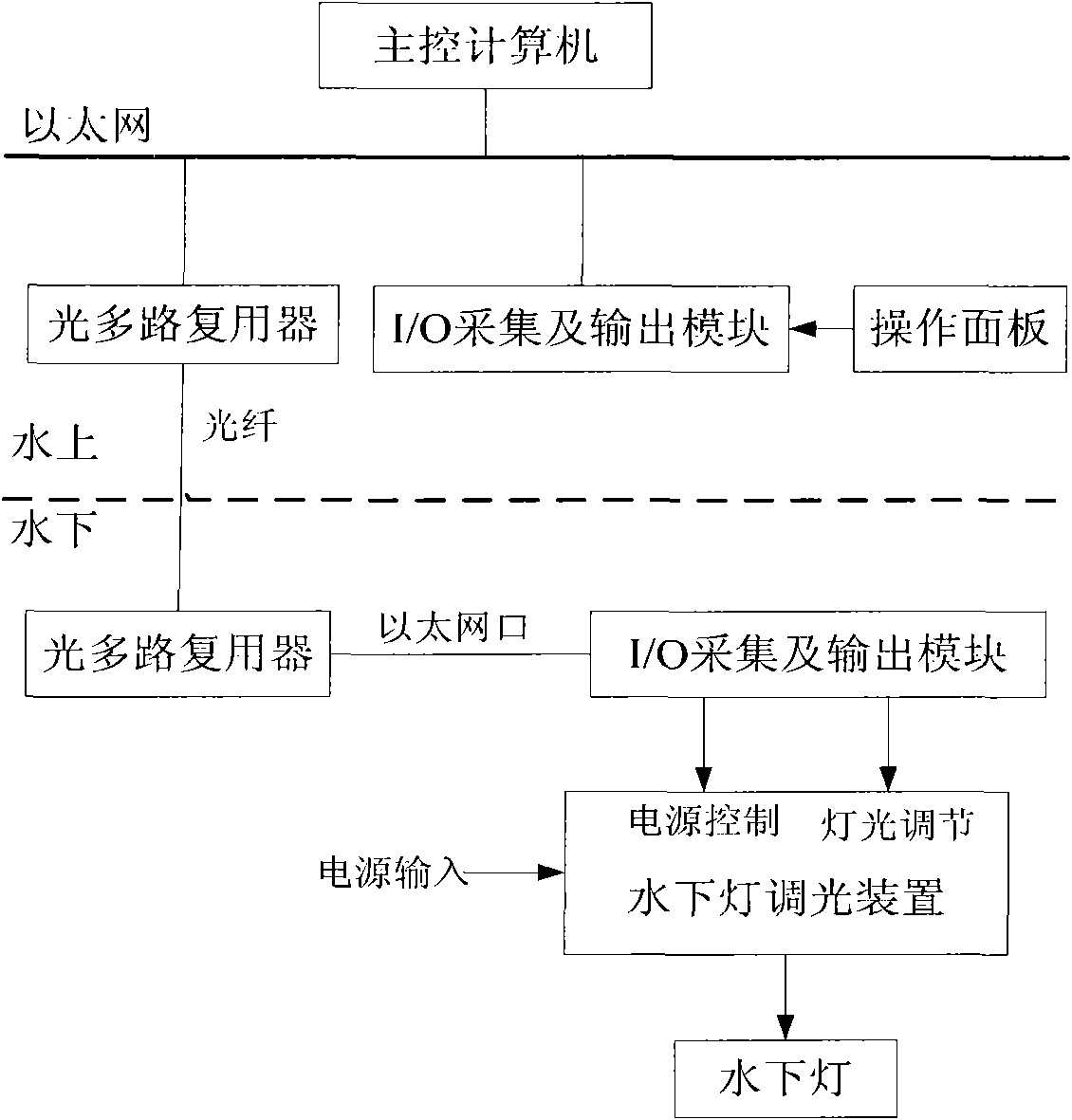
[0021] The underwater lamp dimming system of the present invention adopts optical fiber as the signal communication medium, and both the water surface and the underwater have I / O acquisition and output modules based on Ethernet for signal acquisition and control output, and the underwater lighting is completed under the control of the main control computer on the water surface. Light switch and brightness adjustment.

[0022] Such as figure 1 As shown, the system structure includes an I / O acquisition and output module, a main control computer, and an underwater light dimming device. The main control computer receives control signals from the I / O acquisition and output module on the water surface through Ethernet, and converts the processed The control signal is sent to the underwater I / O acquisition and output module through the optical fiber...


PUM


Abstract

The invention relates to a dimming technology of an underwater lamp of an underwater robot, in particular to a dimming system for remotely dimming the brightness of an underwater lamp arranged on an underwater robot by adopting a digital transmission technology. The dimming system comprises I / O acquisition and output modules, a main control computer and underwater lamp dimming devices and is characterized in that the main control computer receives a control signal from the I / O acquisition and output module on the water surface through an Ethernet and transmits the processed control signal to the I / O acquisition and output module underwater through an optical fiber, the I / O acquisition and output module underwater outputs a power control signal and a light dimming signal to the modularly arranged underwater lamp dimming devices, and the control to the light is realized through a control program in the main control computer. The system has the characteristics of modularization, safe interface and simple design, can realize the continuous control to the light of the single-lamp in the whole range as well as the remote light control and is provided with the interference-free dimming devices.

Description

technical field [0001] The invention relates to a dimming technology for an underwater lamp of an underwater robot, in particular to a dimming system for remotely adjusting the brightness of the underwater lamp on the underwater robot by adopting digital transmission technology. technical background [0002] An underwater robot is a device that works in the sea. There are multiple underwater cameras installed on it. To observe the situation in the sea, the cameras need underwater lights to provide lighting. Due to different sea areas and seasons, the visibility in sea water Different, moreover, as the distance of the camera is different from the object to be observed, the clarity of the image is also different, so the brightness of the lights required by the camera at different positions on the underwater robot is also different. The adjustment of the brightness of the underwater lights on the conventional underwater robot is realized by changing the voltage of the voltage-a...

Claims


Application Information

Patent Timeline
IPC IPC(8): H05B37/02G08C15/00F21S2/00
Inventor 郭威关玉林王晓辉任福林赵洋崔胜国
Owner SHENYANG INST OF AUTOMATION - CHINESE ACAD OF SCI
Why Eureka
Try Eureka