
Aqueous suspension bearings

A suspension bearing and water suspension technology, applied in the field of bearings, can solve the problems such as the inability to meet the high-speed and high-precision requirements of the grinder, the difficulty of the spindle unit accuracy to meet the high-precision requirements, and the inability to meet the requirements of the high-speed grinder, etc., and achieve heat dissipation effect. Good, stable performance, beneficial to environmental protection and the effect of

Inactive Publication Date: 2009-10-07
湖南普来得机械技术有限公司
View PDF0 Cites 3 Cited by
  • Summary
  • Abstract
  • Description
  • Claims
  • Application Information

AI Technical Summary

Problems solved by technology

[0005] Traditional rolling element bearings can meet the requirements of high speed, but the accuracy of the spindle unit is difficult to meet the high precision requirements, and with the increase in use, the rolling elements will be worn and the accuracy of the spindle will decrease, which cannot meet the use of high-speed grinding machines Requirements, the current domestic grinding machine spindle system generally does not use the form of rolling bearings
[0006] Traditional hydrostatic bearings have been widely used on the spindles of precision machine tools such as grinding machines, and can meet the requirements of general speed and precision. However, the spindle oil with a certain pressure provided by the hydraulic station keeps the bearings in working condition. , the spindle oil has a certain viscosity, and it generates heat seriously when working under pressure, so that the working speed of the spindle is greatly restricted, which cannot meet the high-speed and high-precision requirements of the grinding machine

Method used


Image

  • Aqueous suspension bearings
  • Aqueous suspension bearings
  • Aqueous suspension bearings

Examples


Embodiment Construction

[0016] Specific embodiments of the present invention will be described in detail below in conjunction with the accompanying drawings.

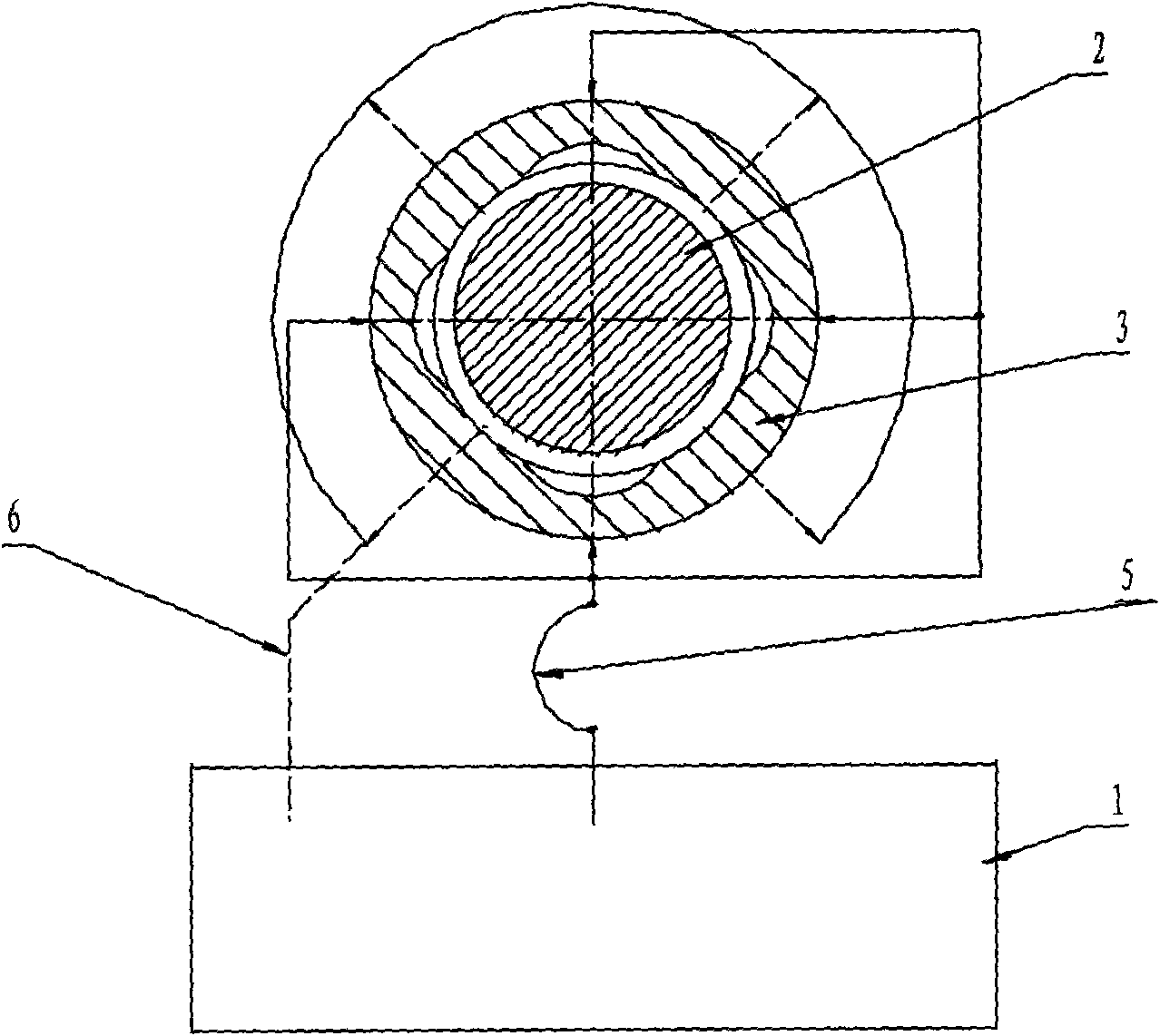
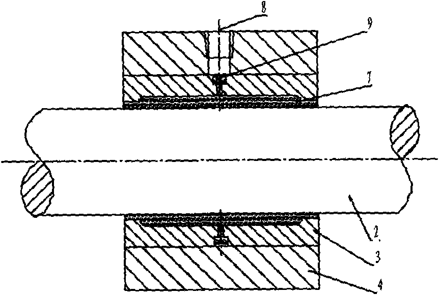
[0017] The present invention is developed on the basis of sliding bearings. The technical scheme of the present invention includes the following three aspects: 1. By means of a hydraulic system, water is forcibly sent between two relatively sliding bearing working surfaces, and the water is used to 2. Relying on the dynamic pressure generated when the main shaft rotates, the system has a greater bearing capacity and has high rotation accuracy, high rigidity, and vibration resistance. Good features; 3. Make full use of the small water-liquid friction coefficient and good heat dissipation, supplemented by refrigeration treatment to solve the cooling problem when the spindle is above 6000 rpm.

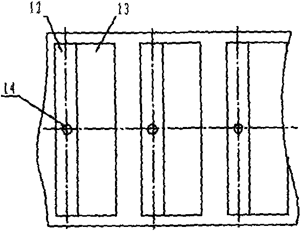
[0018] Such as figure 1 As shown, the present invention is composed of two parts, a water quality hydraulic station 1 and a suspension bearing unit, whe...


PUM

PropertyMeasurementUnit
Depthaaaaaaaaaa
Depthaaaaaaaaaa

Abstract

The present invention relates to bearing, comprising two sections of water hydraulic stations and suspension bearing unit, wherein, the suspension bearing unit employs water as suspension medium, the suspension bearing unit contains principal axis, bearing sleeve, bearing wrap, wherein, a water pressure cavity formed between the principal axis and the bearing sleeve, and upon the bearing wrap is arranged with pressure water entrance, upon the bearing sleeve is arranged with aqueous medium channel to communicate with the pressure water entrance, inner side of the bearing sleeve is provided with at least three groups of aqueous medium pressure deep cavity and pressure shallow cavity distributed centering, each group of aqueous medium pressure deep cavity is also provided with inlet throttle ostiole. Because of using shuiji as suspension bearing medium cau effectively reduce resistance of suspension bearing liquid membrane, additionally the shuiji has good heat radiating effect, which can effectively resolve the heat reaidting problem of ultra-high speed suspension bearing and common suspension bearing. The aqueous suspension bearing can widely used in rotating position of precision machine tools principal axis and precision detection device, and principal axis with ultra-high speed high precision request.

Description

technical field [0001] The invention relates to a bearing widely used in various precision machine tools and testing equipment in the machinery manufacturing industry. Background technique [0002] As an important mechanical basic part for the supporting and maintenance of various electromechanical products, bearings have the characteristics of small friction, easy start-up, rapid speed-up, compact structure, high level of "three modernizations" (standardization, serialization, and generalization), and adapt to various modern The mechanical requirements of the working performance, long service life and easy maintenance and other characteristics, its performance, level and quality have a direct impact on the accuracy and performance of the main engine, and are widely used in various fields of the national economy. [0003] In 1772, C. Wallow of England designed and manufactured ball bearings, and installed them on the mail car for trial use. In 1794, P. Worth of England obta...

Claims


Application Information

Patent Timeline
IPC IPC(8): F16C32/06
Inventor 林厚波吴杰鲁祖荣余军康贵利
Owner 湖南普来得机械技术有限公司
Learn More