
Thermally enhanced solid-state generator

A solid-state energy device and battery technology, applied in the direction of electrochemical generators, capacitors, hybrid capacitors, etc., can solve the problems of no conversion efficiency, not cost-effective, and affecting environmental capital expenditures, etc.

Active Publication Date: 2009-09-30
托马斯·贝雷蒂茨
View PDF3 Cites 1 Cited by
  • Summary
  • Abstract
  • Description
  • Claims
  • Application Information

AI Technical Summary

Problems solved by technology

Other types of energy conversion systems based on wind, hydroelectric, and atomic energy inputs, while cost effective in some cases, negatively impact the environment and / or may require significant capital expenditures
Other more specialized types of power generation devices such as thermoelectric, thermoelectric and magnetohydrodynamic devices do not currently have the necessary conversion efficiencies to make them suitable for large amounts of electricity generation, and in addition, are complex to manufacture
Alternative forms of energy conversion were not cost effective to produce and operate even when circulating oil prices were hovering at $61 / barrel on October 2, 2006

Method used


Image

  • Thermally enhanced solid-state generator
  • Thermally enhanced solid-state generator
  • Thermally enhanced solid-state generator

Examples


Embodiment Construction

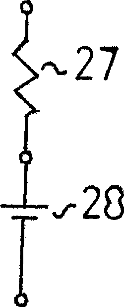
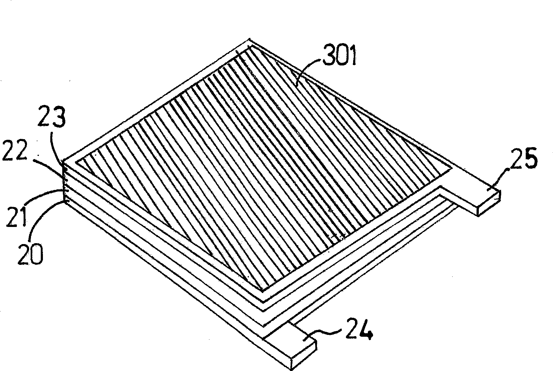
[0079] The present invention, a new type of electrical energy generating device, is based on the purposeful layering of different materials - oxides, semiconductors, metals and carbon, so that a voltage difference appears at the interface of each material and the total voltage value is presented between the positive and negative terminals of the device. Electricity is generated from the device by developing a built-in potential across the interface between stable materials with different electronic structures and densities. Once the layers are properly aligned, the device can be treated as any electrical device and stacked in series or parallel to achieve the desired voltage output or current output.

[0080] The electrons oscillate and emit electromagnetic energy in waves. These waves have a frequency distribution based on Planck's formula. Likewise, because of the connections between atoms, the migration of one or more atoms from their equilibrium position will create a se...


PUM

PropertyMeasurementUnit
melting pointaaaaaaaaaa

Abstract

A solid state energy conversion device along with its production methods and systems of use is provided. The device in its most basic form consists of two layers, in contact with each other, of dissimilar materials in terms of electron density and configuration, sandwiched between metal layers, which serve as the anode and cathode of the device. One of the inside layers is made of a stabilized mixture of carbon and an ionic material (carbon matrix). The other inner material consists of a stabilized oxide mixed with an ionic material (oxide matrix). This device takes advantage of the built-in potential that forms across the barrier between the carbon matrix and the oxide matrix. The built-in potential of the device (when not attached to a resistive load at the terminals), which is determined mathematically by integrating the electrostatic forces that have created themselves across the barrier, will rise or fall in direct proportion to the rise and fall of the device temperature (in kelvins). When a load is attached across the terminals of the device, current flows. Depending on the size of the load or the surface area of the device, a reduced current will allow sustained recombination such that the built-in potential and current remains steady overtime. Otherwise, the current curve will fall over time similar to a capacitor device. Experimentation shows that current rises by the fourth power of the temperature factor.

Description

[0001] Cross References to Related Applications [0002] This application claims the benefit of priority to US Provisional Application No. 60 / 454,511, filed October 5, 2005, the disclosure of which is hereby incorporated by reference. [0003] Federally Funded Research: Not Applicable [0004] Sequence Listing: Not Applicable technical field [0005] The present invention relates to the generation of electrical energy by solid-state devices, and more particularly, to the generation of electrical energy by the use of voltage sources of thermally enhanced built-in potentials generated at junctions between dissimilar materials, unlike Materials include metals, semiconductors, ceramics (oxides, carbides, etc.), and carbons (graphite, charcoal). Background technique [0006] Electrical energy generating devices utilize energy inputs including, but not limited to, electromagnetic waves (sunlight, infrared light, etc.), thermal energy, mechanical energy, and atomic energy, and th...

Claims


Application Information

Patent Timeline
Patent Type & Authority Applications(China)
IPC IPC(8): H01G9/21H01M10/39
CPCY02E60/12H01M10/0413H01M10/39H01G11/38H01M4/58H01G11/02H01M2300/002H01G11/58Y02E60/13H01M2300/0048H01M4/48H01M4/50H01M4/661H01M4/583H01G11/86H01G9/058H01G11/46H01G11/04H01G9/155Y02T10/7022H01M6/50H01G9/22H01G9/21Y02T10/70Y02E60/10Y02P70/50
Inventor 托马斯·贝雷蒂茨
Owner 托马斯·贝雷蒂茨
Learn More