Automatic buffer device of automobile clutch

A buffer device and clutch technology, applied in the field of automobile transmission, can solve problems such as uneven start, personnel and mechanical damage, and poor follow-up performance, and achieve the effects of solving poor follow-up performance, improving safety performance, and reducing the driver's difficulty in operation

Inactive Publication Date: 2009-09-30
袁力杰
View PDF0 Cites 3 Cited by
  • Summary
  • Abstract
  • Description
  • Claims
  • Application Information

AI Technical Summary

Problems solved by technology

[0003] The purpose of the present invention is to design an automatic buffer device for automobile clutches for the above-mentioned problems of poor follow-up of the existing automobile clutches, unstable starting, and possible damage to personnel and machinery.

Method used


Image

  • Automatic buffer device of automobile clutch
  • Automatic buffer device of automobile clutch
  • Automatic buffer device of automobile clutch

Examples


Embodiment Construction

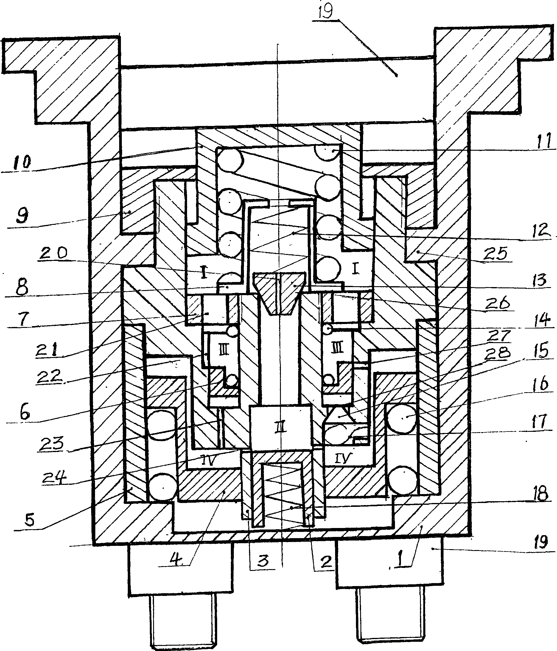
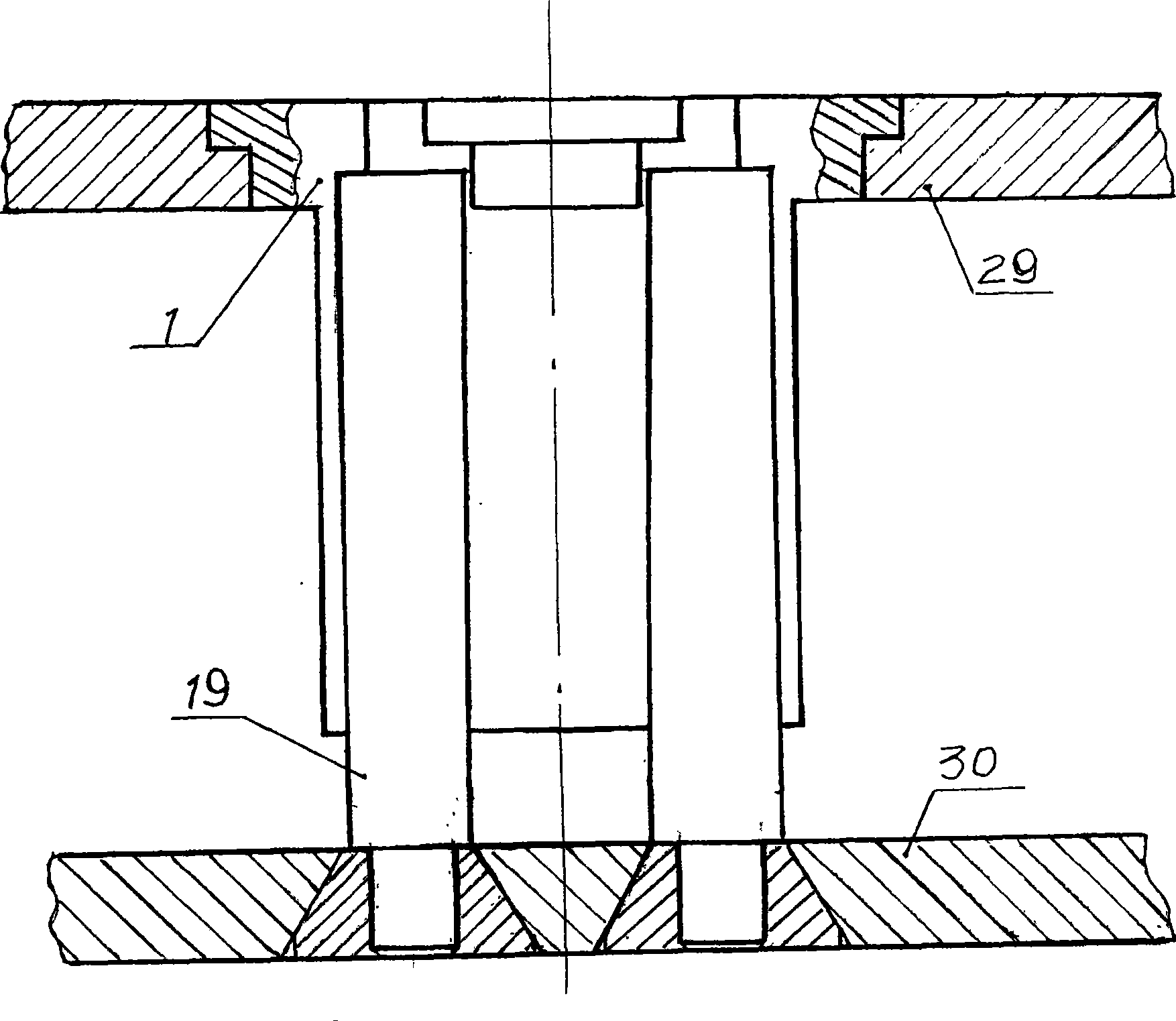
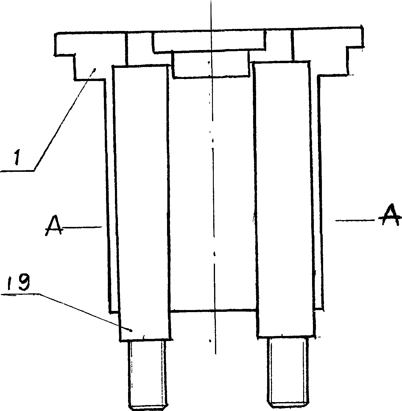
[0011] combine figure 1 and Figure 5 Described as follows, the automatic buffer device of the automobile clutch of the present invention is installed between the clutch cover and the pressure plate. The pressure of the pressure bowl 19 on the upper piston 10 is canceled, and the upper piston 10 pops up under the action of the upper plug spring 11, so that a negative pressure of about 1 kg is generated in the No. I oil cylinder, and the valve 26 is under this negative pressure and the lower positive pressure. The large valve block 13 overcomes the pressure of the large valve spring 12 and moves upward, and the bottom piston 2 in the No. II oil cylinder moves upward under the action of the above-mentioned negative pressure and the bottom plug spring 18 until it stops at the upper limit position, thereby pushing The upper piston 10 moves upwards. At this time, the negative pressure in the No. I oil cylinder still exists. Because the No. I oil cylinder communicates with the No. ...


PUM


Abstract

An automatic buffer device of car clutch settles a problem of inferior following characteristic of clutch and increases the safety in starting-up and stage changeover. The invention is characterized in that a bearing container and a press container sleeve with each other to form a slidable casing of the device. The bearing cylinder and total cylinder in the casing are cylinders for filling oil fluid. The total cylinder is provided with a small opening and a groove. The upper gear and the middle gear are the cylinder heads of I and III oil cylinders. The upper gear is installed on the boss at the inner wall of bearing container. The middle of upper gear is provided with a round opening. The upper piston extends out from the round opening. The middle gear is installed with eight small openings. A large valve block and the upper opening of II oil cylinder form a valve. A small opening is installed on the large valve block. Four small valve block and four round openings at the lower part of III oil cylinder form four valves. An upper piston and an upper plunger spring are installed in the I oil cylinder. A base piston and a base plunger spring are installed in the II oil cylinder. A middle piston and a middle plunger spring are installed in the III oil cylinder. A lower piston is installed in IV oil cylinder. A lower plunger spring is installed in the bearing cylinder. A buckle cup is installed on the upper part of middle gear. A large valve spring is installed in the buckle cup. An upper plunger spring is installed outside the buckle cup.

Description

technical field [0001] The invention belongs to the automobile transmission technology, and in particular relates to an automatic buffer device for an automobile clutch. Background technique [0002] The automobile clutch is one of the connecting parts in the automobile transmission system. It is composed of active parts, driven parts, compression springs and operating mechanisms. It transmits power by friction and is used for starting, parking, shifting and other working processes . The clutch is realized by the driver's pedal, that is, depressing to separate and lifting to combine. In the clutch process of the transmission device, it is mainly operated by the driver's feeling. When the known large-scale passenger and truck step on the clutch, the stepping force is large, so the power assist system is used, but the drive process of the power assist system lags behind, causing the driver to step on It feels out of sync with the actual clutch position, so the car often appe...

Claims


Application Information

Patent Timeline
Patent Type & Authority Applications(China)
IPC IPC(8): B60K23/02F16D48/02
Inventor 袁力杰
Owner 袁力杰
Why Eureka
Try Eureka