
Bipolar driving linear motor

A linear motor and pole drive technology, applied in the direction of synchronous machines, electrical components, electromechanical devices, etc., can solve the problems of inability to generate an air gap magnetic field at both ends of the winding, difficult processing, etc., achieve good heat dissipation conditions, high magnetic field utilization, and improve The effect of machining accuracy

Inactive Publication Date: 2009-09-23
DALIAN UNIV OF TECH
View PDF0 Cites 3 Cited by
  • Summary
  • Abstract
  • Description
  • Claims
  • Application Information

AI Technical Summary

Problems solved by technology

[0007] The second purpose of the present invention is to overcome the disadvantages that the silicon steel sheet of the prior art is integral, difficult to process, and cannot generate an air gap magnetic field at both ends of the winding, and the iron core block used is made of silicon steel sheets, and the wires are wound on The waist of the iron core block, the air gap magnetic field is generated at both ends of the iron core block

Method used


Image

  • Bipolar driving linear motor
  • Bipolar driving linear motor
  • Bipolar driving linear motor

Examples


Embodiment Construction

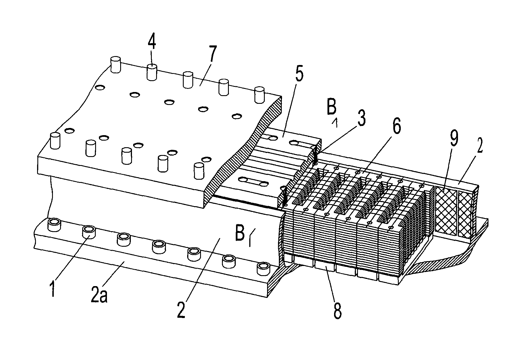
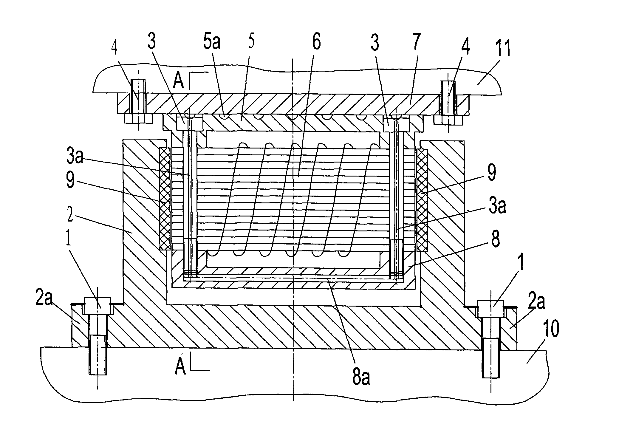
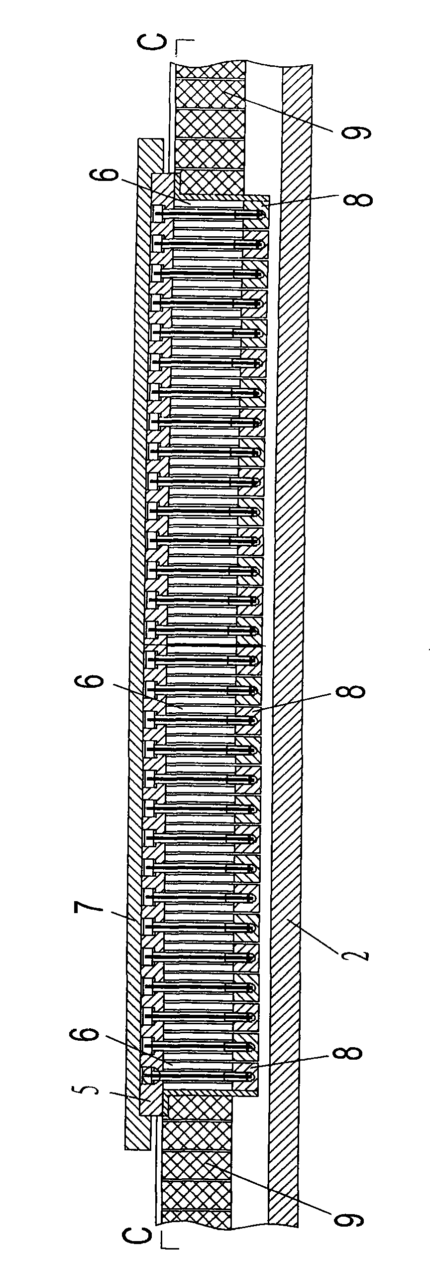
[0023] figure 1 , 2 The main structure of a bipolar driven linear motor is shown. The secondary part of the linear motor is a U-shaped trough-shaped part 2 installed on the supporting part 10, and permanent magnet materials 9 are pasted on the inside of both sides of the U-shaped trough-shaped part 2, and the primary part is installed on the opposite secondary part. The part of the iron core block 6 with the winding coil on the part 11 that moves linearly, the iron core block 6 is located between the permanent magnet materials 9 on both sides of the U-shaped groove part 2, and the part 11 that can move along the line Move along the U-shaped groove. The lower part of each iron core block 6 is provided with an iron core block pressing plate 8 , and the upper part is provided with a cooling plate 5 , and then they are fastened together by connecting bolts 3 . On the upper plane of the cooling plate 5 is provided a cooling groove 5 a closed by the first connecting plate 7 , and...


PUM


Abstract

The invention relates to a bipolar driving linear motor belonging to the field of electric drive. A secondary part of the linear motor is in a U-shape groove shape, and permanent magnetic materials are attached to the inner sides of both sides of the U-shaped groove; a primary part comprises a plurality of iron core blocks which are positioned among the permanent magnetic materials positioned at both sides of the U-shape groove, the parts which can move following a straight line move along the U-shape groove, and the circumference of each iron core block is provided with a circulating cooling passage. The bipolar driving linear motor has high output power and high magnetic field utility ratio, thereby having high efficiency; the bipolar driving linear motor is easy to manufacture a low-speed high-thrust linear motor; the bipolar driving linear motor is provided with the circulating cooling passage, thereby having good radiating condition without causing the heat distortion of a machine tool and being beneficial to enhancing the processing precision of the digital control machine tool; the secondary part is in a U-shape groove shape, the permanent magnetic materials are attached to both sides of the U-shaped groove, the up and down position relation between the primary part and the secondary part is loosely required, air gaps of a magnetic field are more than 1 millimeter, and the precision is loosely required, thus the bipolar driving linear motor has convenient processing and assembly.

Description

technical field [0001] The invention relates to a bipolar driven linear motor, which belongs to the linear permanent magnet synchronous AC motor in the field of electric drive. Background technique [0002] The current commonly used linear motor is similar in principle to the ordinary motor, which can be regarded as a cylindrical motor that is cut and flattened along the radial direction. The part that is wound with a wire to generate a moving magnetic field is called the primary, and the part that is induced by the moving magnetic field is called the secondary. The types are also the same as ordinary motors, including DC linear motors, AC permanent magnet synchronous linear motors, AC induction asynchronous linear motors, stepping linear motors, etc. [0003] Linear motors can be used as power components to directly generate linear motion in many occasions, instead of having to go through gear racks, screw nuts and other mechanisms to generate linear motion like cylindrica...

Claims


Application Information

Patent Timeline
Patent Type & Authority Applications(China)
IPC IPC(8): H02K21/00H02K21/02H02K3/46H02K9/00
Inventor 杨有君杨振强梁延德
Owner DALIAN UNIV OF TECH
Learn More