Eureka AIR delivers breakthrough ideas for toughest innovation challenges, trusted by R&D personnel around the world.

Exhaust gas treatment method and incinerator used for steel plate color-coating line

A technology for waste gas treatment and color coating line, which is applied in the field of incinerators and can solve problems such as energy waste, environmental damage, and environmental pollution.

Inactive Publication Date: 2009-09-23
福建凯景新型科技材料有限公司
View PDF0 Cites 17 Cited by
  • Summary
  • Abstract
  • Description
  • Claims
  • Application Information

AI Technical Summary

Problems solved by technology

[0002] At present, there are generally two types of waste gas emissions from the steel plate color coating line: one is direct emission, which will cause great pollution to the environment and waste of energy. Burning carbon; the second is to discharge after burning in an incinerator, which can reduce pollution, but there are still about 3% to 5% of organic solvents and NO in the discharged waste gas. X smoke, causing environmental damage

Method used


Image

  • Exhaust gas treatment method and incinerator used for steel plate color-coating line
  • Exhaust gas treatment method and incinerator used for steel plate color-coating line
  • Exhaust gas treatment method and incinerator used for steel plate color-coating line

Examples


Embodiment Construction

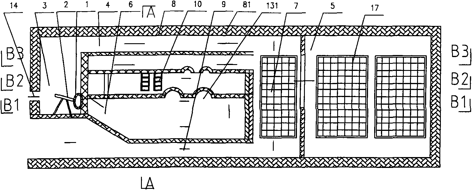
[0019] In the present invention, the waste gas containing organic solvents generated after heating the steel plate is preheated through a furnace bottom channel and the rear and upper parts of the incinerator, and then enters the incinerator with a furnace temperature of 600-800 ° C, and is passed through contact with gas and combustion-supporting air. For direct combustion, the flow rate of the treated exhaust gas in the incinerator is controlled to be greater than 5 seconds. The length of the combustion channel of the incinerator should ensure that the waste gas stays in it for more than 1 second.

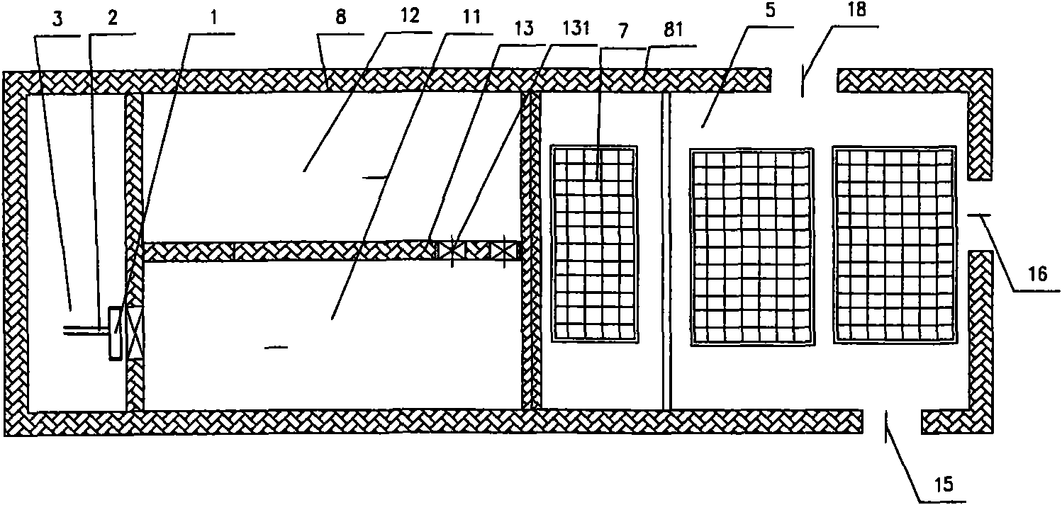
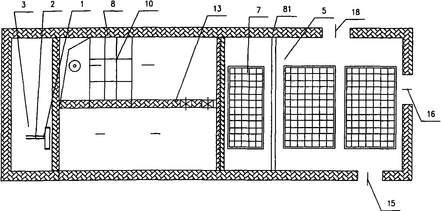
[0020] In order to realize above-mentioned control method, the present invention provides a concrete incinerator embodiment, see Figure 1 to Figure 5 . figure 1 The transverse section structure of the incinerator described in the utility model is illustrated; Figure 2-Figure 4 The cross-sectional structures along the B1-B1, B2-B2, and B3-B3 layers of the incinerator are respe...


PUM


Abstract

The invention discloses an exhaust gas treatment method and an incinerator used for a steel plate color-coating line. The method comprises the step of: completely burning the exhaust gas which is directly discharged or discharged after traditional secondary burning under the conditions that the temperature is higher than 650 DEG C, the residence time is more than 1 second, and the flow rate is larger than 5 m / s. The incinerator comprises a furnace shell, an exhaust gas channel arranged in the furnace shell, a burner, a porous absorptive heat accumulator and a heat exchanger; a pre-heating chamber, a main burning chamber and a secondary burning chamber are arranged on the exhaust gas channel in sequence; the pre-heating chamber is arranged at the front part of the exhaust gas channel; the main burning chamber and the secondary burning chamber are arranged in the middle of the exhaust gas channel in sequence; the burner is arranged at an inlet of the main burning chamber; the porous absorptive heat accumulator is arranged above the secondary burning chamber; and the heat exchanger is arranged at the rear part of the exhaust gas channel. The invention can further reduce pollution emission, leads the organic solvent and part of incompletely burned exhaust gas to be fully burned, generates non-polluting carbon dioxide and water, and then implements heat exchange with fresh air by the heat exchanger and finally discharge the product.

Description

technical field [0001] The invention relates to a waste gas treatment method and an incinerator for a steel plate color coating line. Background technique [0002] At present, there are generally two types of waste gas emissions from the steel plate color coating line: one is direct emission, which will cause great environmental pollution and waste of energy. At the same time, due to direct heating, some organic solvents will remain on the surface of the finished color coated steel plate, Burning carbon; the second is to discharge after burning in an incinerator, which can reduce pollution, but there are still about 3% to 5% of organic solvents and NO in the discharged waste gas. X smoke, causing environmental damage. Contents of the invention [0003] The object of the present invention is to provide a waste gas treatment method and an incinerator for a steel plate color coating line that can further reduce pollution discharge. [0004] A waste gas treatment method for ...

Claims


Application Information

Patent Timeline
IPC IPC(8): F23G7/06
Inventor 陈振常陈政贤林顺发
Owner 福建凯景新型科技材料有限公司
Why Eureka
Eureka Blog
Learn More