
Foundation for a wind turbine

A technology for wind turbines and generators, which is applied to wind turbines, wind turbines in the same direction as the wind, engines, etc., which can solve the problems of wind turbine generator unit cost reduction and size increase, so as to reduce excavation costs and reduce formwork and the effects of simplification and increased stability

Inactive Publication Date: 2009-09-23
GAMESA INNOVATION & TECH SA
View PDF11 Cites 1 Cited by
  • Summary
  • Abstract
  • Description
  • Claims
  • Application Information

AI Technical Summary

Problems solved by technology

To this end, the size of the foundation used to support the turbine generator above has to be increased, so that the reduction in the use of material for the foundation results in a considerable reduction in the cost of the wind turbine generator unit

Method used


Image

  • Foundation for a wind turbine

Examples


Embodiment Construction

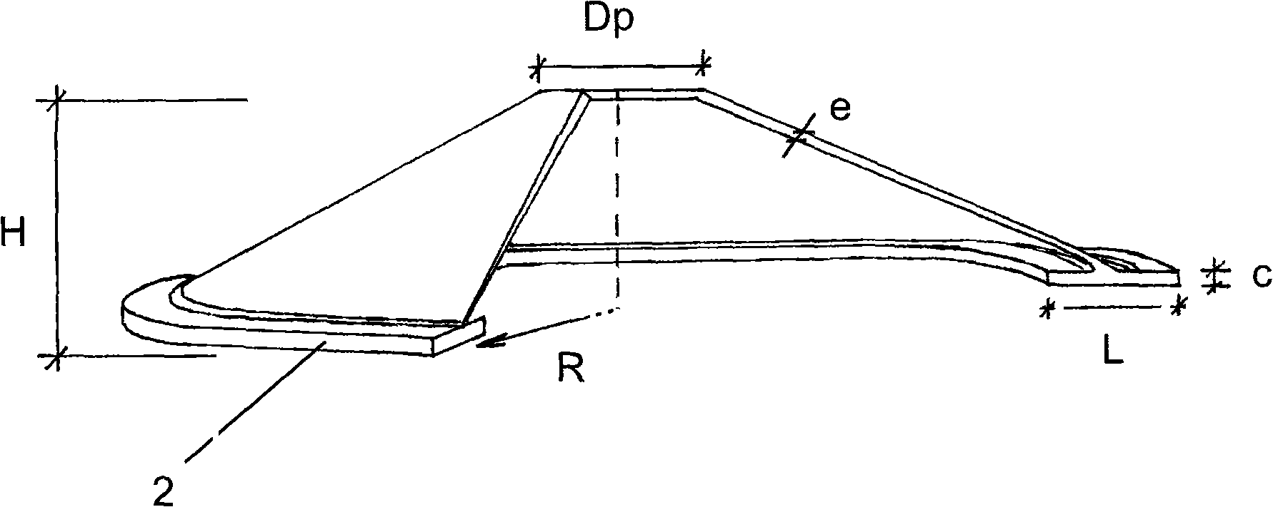
[0048] In the present invention, the cone foundation is based on a cone shape with a base plate (2) capable of bearing the stresses on the walls of the cone (1) and transferring them to the ground. Sometimes a base not shown here is used above the cone to connect the foundation to the tower, in other embodiments perhaps a concentric ring in the form of a flange is used to allow access to the hollow interior of the foundation.

[0049] In an approach similar to inertial foundations, where the radius of the cone creates inertia at its base, stresses can be smoothly transferred across the conical surface from the base of the tower to the supporting ground.

[0050] There are two main variants of this design, and one minor variant:

[0051] ◆Filled conical foundations involved in the preferred embodiment of the invention. Since the soil is not excavated from the inside, the conical surface wall (1) rests on this soil, so less stress occurs on the wall because there is no local be...


PUM


Abstract

This invention comprises a wind turbine foundation with a hollow central body in the shape of a truncated cone which has an upper flange or a pedestal to connect with the tower (not shown), and a lower slab in the shape of a plane ring. In the preferred embodiment, the foundation leans the interior surface of the cone and the lower slab on earth from the local terrain, which takes on the role of permanent formwork; in an alternative embodiment, the interior of the foundation is left hollow and accommodates components of the wind turbine within it; and in a final alternative embodiment, the foundation is placed over the surface of the terrain which supports only the base of the lower slab, the central body not being buried.

Description

technical field [0001] The present invention generally relates to a conical wind turbine generator foundation comprising, in particular, a frusto-conical central body and an oblate annular base plate with an upper flange or base for connection to the tower above the central body. shelf. Background technique [0002] The power produced by a wind turbine generator is directly proportional to the size of the rotor. Therefore, in order to generate greater power, the size of the blades needs to be increased, with the result that the dimensions of the drive train, turbine generator and tower height increase. To this end, the size of the foundation for supporting the turbine generator above has to be increased, so that a reduction in the material used for the foundation results in a considerable reduction in the cost of the wind turbine generator unit. In this regard, the technologies described above offer a number of basic options for more challenging requirements, reducing raw ...

Claims


Application Information

Patent Timeline
Patent Type & Authority Applications(China)
IPC IPC(8): F03D1/00E02D27/42
CPCE02D27/42E02D27/32
Inventor 卡洛斯·里昂·佩费克托
Owner GAMESA INNOVATION & TECH SA
Learn More