Pipe gas flow crushing device
A technology of airflow crushing and pipeline, which is applied in the field of pipeline airflow crushing device for fly ash, which can solve the problems of high drive motor power and high energy consumption, and achieve the effects of low operating noise, simple system and low investment
Inactive Publication Date: 2009-09-09
HUNAN ELECTRIC POWER POWDERED COAL ASH COMPLEX UTILIZATION DEV
View PDF0 Cites 0 Cited by
- Summary
- Abstract
- Description
- Claims
- Application Information
AI Technical Summary
Problems solved by technology
Due to the heavy weight of the ball mill and the metal ball itself, the required driving motor power is also very large, ranging from several hundred to more than one thousand kilowatts, and the energy consumption is extremely high.
Method used
View moreImage
Smart ImageViewing Examples


Examples
Embodiment Construction
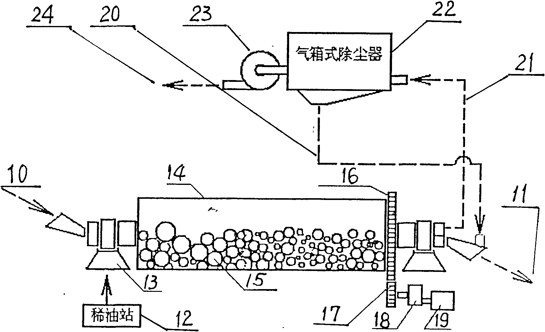
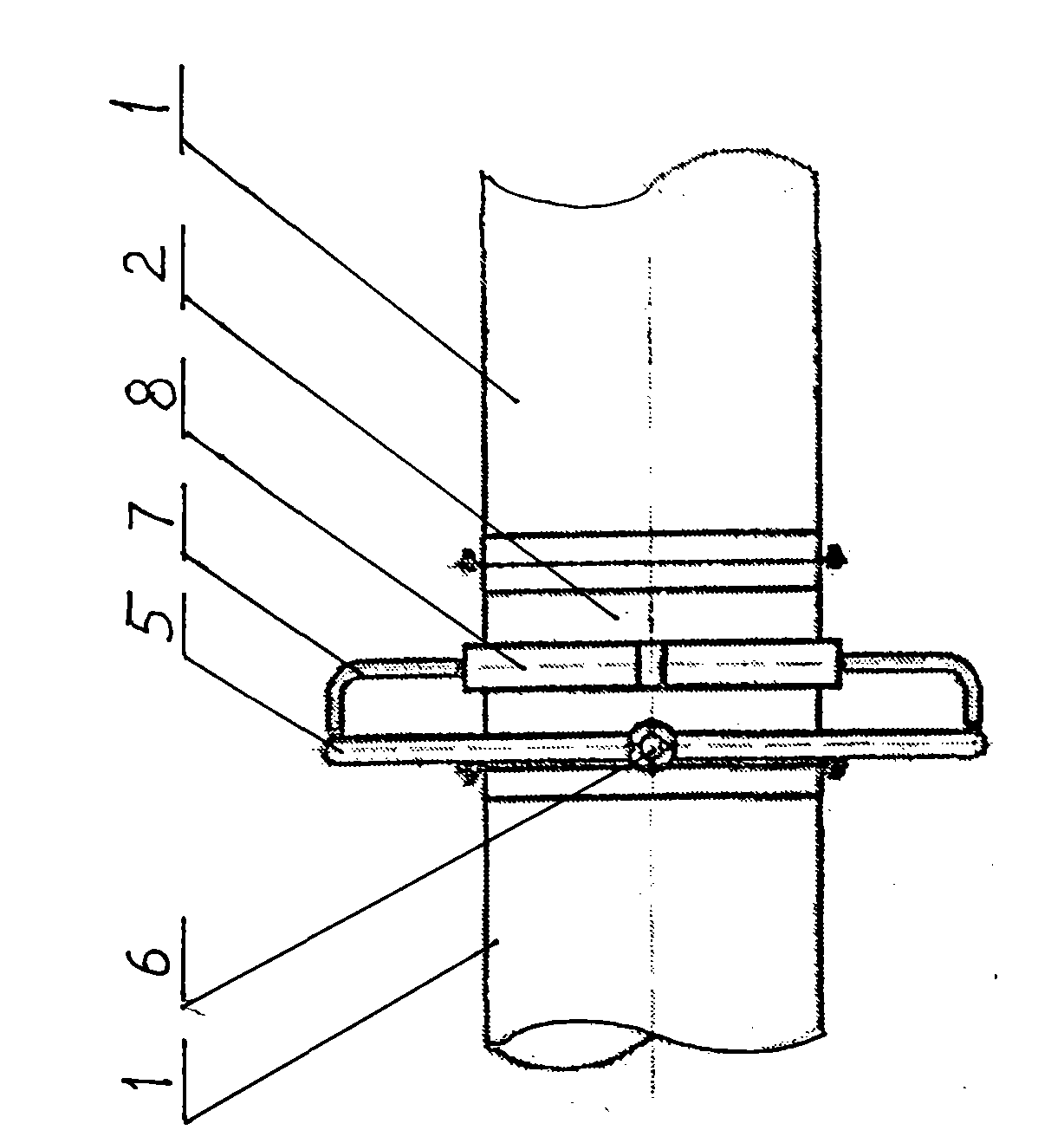
[0037] Referring to the accompanying drawings, this pipeline airflow crushing device is a section of pipeline with a spray gun ring. The ring pipe, the air compressor is connected to the O-ring pipe through the compressed air pipeline, and the O-ring pipe is connected to the nozzles through the radial branch pipes, and the nozzles spray super high-speed or subsonic airflow into the pipe.
Login to View More PUM
 Abstract
A pipe gas flow crushing device is a section of pipe with a spray gun ring, wherein the two ends of the pipe are in sealed joint with fly ash gas flow pipes, the spray gun ring is provided with a plurality of nozzles, the periphery of the pipe is provided with an O-shaped annular pipe, an air compressor is connected and communicated with the O-shaped annular pipe through a compressed air pipe, the O-shaped annular pipe is communicated with the nozzles through radial branch pipes, and the nozzles spray ultra high speed gas flows into the pipes. The device remarkably saves energy, occupies extremely small floor area, and is high in fine powder amount, simplified in process, good in sealing and environment-protection performance, simple in structure, and low in investment and production cost.
Description
Technical field: [0001] The invention relates to a material crushing device, in particular to a pipeline airflow crushing device for fly ash. Background technique: [0002] The traditional fly ash crushing method is to use a ball mill to grind the fly ash. see Figure 4 The schematic diagram of the ball mill structure is shown. The main body of the ball mill is cylindrical, that is, a rotating cylinder with a diameter of 1 to 3 meters and a length of several meters to more than ten meters. It is hollow and placed horizontally on the bearing bush. When grinding, 50% of the cylinder cavity The space is filled with fly ash and wear-resistant metal balls (several tons to nearly a hundred tons), and an external high-power high-voltage motor is used to drive the cylinder to rotate at a low speed through a reduction box. The impact and the friction between each other realize the fine grinding of fly ash. Because the weight of the ball mill and the metal ball itself is very large,...
Claims
Login to View More Application Information
Patent Timeline
 IPC IPC(8): B02C19/06
Inventor 石峰管国华
Owner HUNAN ELECTRIC POWER POWDERED COAL ASH COMPLEX UTILIZATION DEV
Features
- R&D
- Intellectual Property
- Life Sciences
- Materials
- Tech Scout
- Unparalleled Data Quality
- Higher Quality Content
- 60% Fewer Hallucinations
Learn More Browse by: Latest US Patents, China's latest patents, Technical Efficacy Thesaurus, Application Domain, Technology Topic, Popular Technical Reports.
© 2025 PatSnap. All rights reserved.Legal|Privacy policy|Modern Slavery Act Transparency Statement|Sitemap|About US| Contact US: help@patsnap.com