
Operating element

A technology for operating components and components, applied in electrical components, pulse technology, electronic switches, etc., to solve problems such as poor observation of operating units

Inactive Publication Date: 2009-09-02
CONTINENTAL AUTOMOTIVE GMBH
View PDF0 Cites 1 Cited by
  • Summary
  • Abstract
  • Description
  • Claims
  • Application Information

AI Technical Summary

Problems solved by technology

However, this arrangement of the operating unit has the disadvantage that the operating unit is only very poorly visible
Therefore the driver often touches and selects the operating elements of the operating unit without visual contact

Method used


Image

  • Operating element
  • Operating element
  • Operating element

Examples


Embodiment Construction

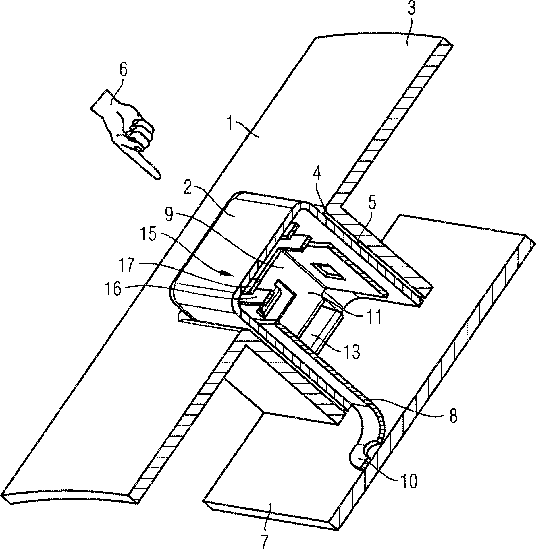
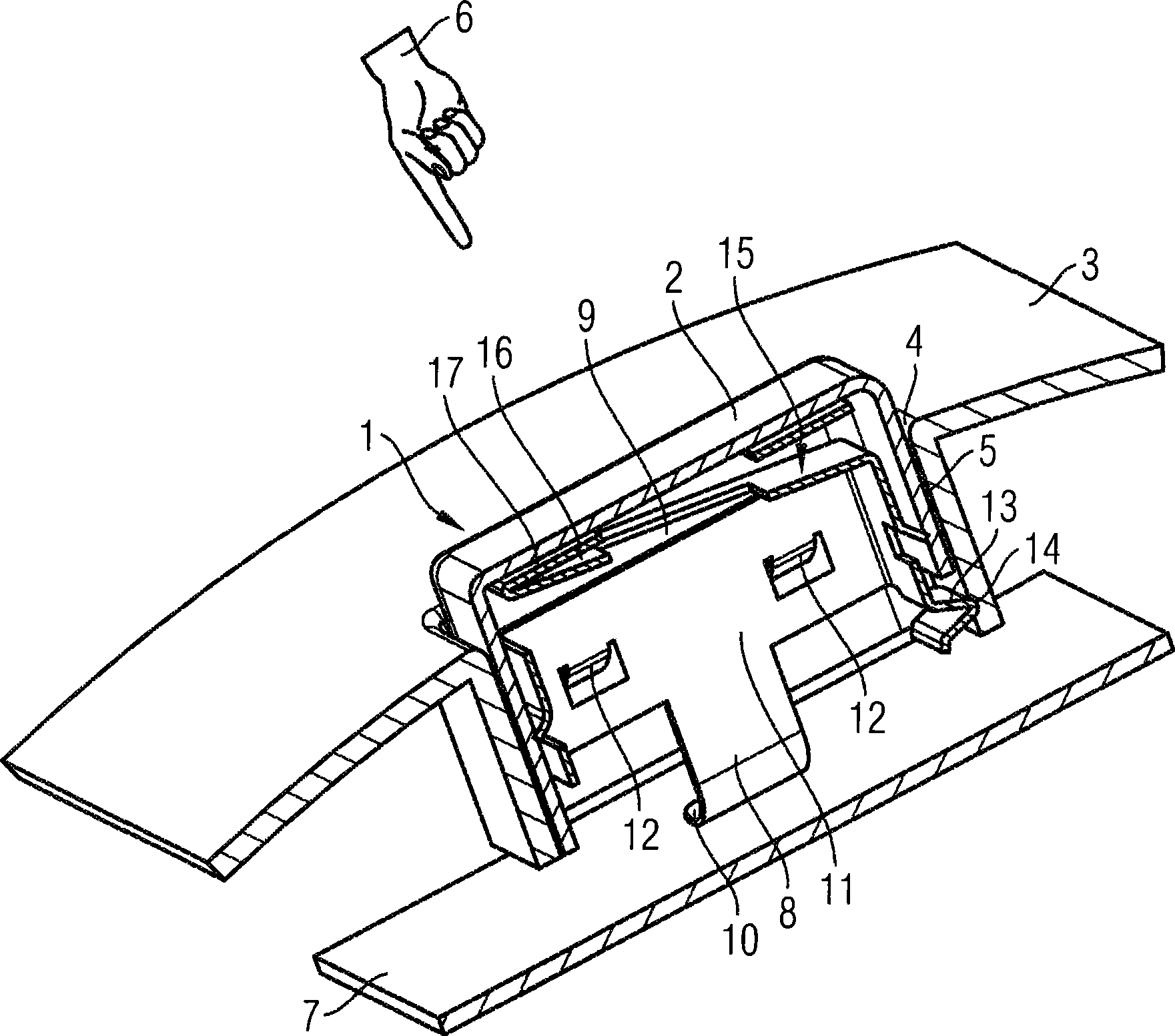
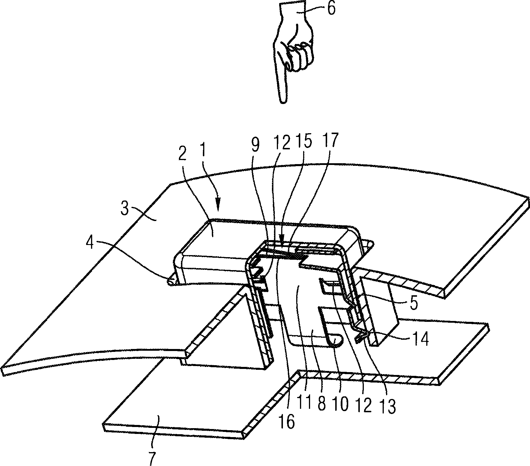
[0042] An opening 4 is formed on the fixed flap 3 , from which a guide channel 5 proceeds to the side opposite the actuating side. The actuation side is shown symbolically by the actuation hand 6 . The guide channel 5 reaches as far as a free-standing printed circuit board 7 approximately parallel to the baffle 3 .

[0043] The contact tongue 8 of the carrier part 11 extending perpendicularly to the circuit board 7 rests with its bent end 10 on a circuit board track (not shown) of the circuit board 7 and is fixedly connected to the circuit board 7 .

[0044] At the same time, the contact tongue 8 , which forms the return spring, is designed in one piece with a frame-like support part 11 designed as a plate / bent part, which is inserted into the guide channel 5 . The basin-type actuating part 1 is installed on the support part 11 from the actuating side, the bottom of the actuating part forms the keying plate 2 which can be pressed by the operator, and the actuating part is ins...


PUM


Abstract

The invention relates to an operating element having an actuating element (1) disposed on a linear moving carrier element (11), the actuating element having a plate-like touch panel (2) that can be manually applied to its plate side, and that is made of an electrically nonconductive material, which cooperates with a switching element, and wherein an electrically conductive sensor element of a capacitative proximity sensor is disposed. The sensor element of the proximity sensor is disposed on or in the touch panel (2).

Description

technical field [0001] The invention relates to an operating part, in particular for a motor vehicle assembly, having an actuating part arranged on a linearly movable support part, the actuating part having a plate-shaped A key plate pressed on the side of the plate, the key plate is made of non-conductive material, the actuating part acts on the switching element and in which the conductive sensor element of the capacitive proximity sensor is arranged, the The sensor element is electrically conductively connected to the circuit board. Background technique [0002] Control and display devices, which are ergonomically arranged in the vehicle, are frequently used to operate motor vehicle components such as radio equipment, navigation equipment, vehicle telephones, multimedia devices and the like. The display device should be arranged in such a way that the driver can view it with the least possible deviation from the road traffic. The display unit is therefore preferably arr...

Claims


Application Information

Patent Timeline
Patent Type & Authority Applications(China)
IPC IPC(8): H03K17/96
CPCH03K2217/96054H03K17/965H03K17/962H03K2217/96076
Inventor 迪尔克·维斯藤贝克尔
Owner CONTINENTAL AUTOMOTIVE GMBH
Learn More