Superconducting magnet with quench protection circuit
What is Al technical title?
Al technical title is built by PatSnap Al team. It summarizes the technical point description of the patent document.
A superconducting magnet and quench protection technology, applied in emergency protection circuit devices, superconducting magnets/coils, circuits, etc., can solve the problems of superconductor mechanical performance damage, heat dissipation, extension, etc., to avoid the degradation of superconducting wires, The effect of improving work efficiency and prolonging service life
Active Publication Date: 2011-06-29
TIANSHUI ELECTRIC DRIVE RES INST
View PDF0 Cites 0 Cited by
Summary
Abstract
Description
Claims
Application Information
AI Technical Summary
This helps you quickly interpret patents by identifying the three key elements:
Problems solved by technology
Method used
Benefits of technology
Problems solved by technology
[0006] The current protector or protection circuit has obvious disadvantages: First, most of the heat generated during the quench process is dissipated in the superconductor, and the rapid change of thermal stress will damage the mechanical properties of the superconductor
Excessive temperature will degrade the superconducting wire, causing the critical current to decrease, etc.
High temperatures can also damage the insulating material on the outer layer of superconducting wires
Second, superconducting materials generally work at a low temperature of about 10K. Using a heater will greatly increase the thermal load of the cooling system, prolong the time for re-entering the superconducting state after quenching, and reduce the overall machine efficiency.
Method used
Image
Click on the blue label to locate the original text in one second.
Reading with bidirectional positioning of images and text.
Examples
Embodiment Construction
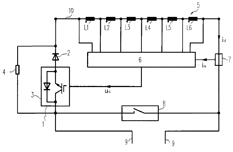
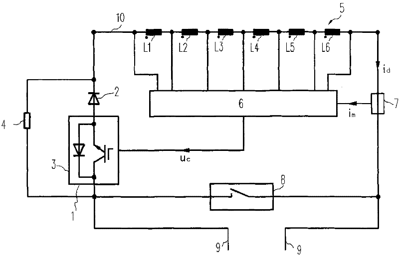
[0014] like figure 1 The present invention as shown provides a superconducting magnet quench protection circuit 1 and a superconducting magnet 10 with the protection circuit 1, the superconducting magnet quench protection circuit 1 includes a diode 2, an insulated gate bipolar transistor 3 and The energy leakage resistor 4 is connected in parallel with the energy leakage resistor 4 after the diode 2 is connected in series with the insulated gate bipolar transistor 3 .
[0015] The superconducting magnet 10 includes a superconducting magnet body 5 composed of at least six series superconducting coils L1-L6, equipped with the above-mentioned superconducting magnet quench protection circuit 1, quench detector 6, current sensor 7, short circuit 8 and a current injection wire 9, one end of the superconducting magnet body 5 in the superconducting magnet 10 is connected to one end of the short circuit 8 through the current sensor 7, and the other end of the superconducting magnet bod...
PUM
Abstract
The invention discloses a superconducting magnet quench protection circuit and a superconducting magnet with the same. The superconducting magnet quench protection circuit comprises a diode, an insulaThe invention discloses a superconducting magnet quench protection circuit and a superconducting magnet with the same. The superconducting magnet quench protection circuit comprises a diode, an insulated-gate bipolar transistor and an energy leakage resistor, and the diode is serially connected with the insulated-gate bipolar transistor and then is parallelly connected with the energy leakage resited-gate bipolar transistor and an energy leakage resistor, and the diode is serially connected with the insulated-gate bipolar transistor and then is parallelly connected with the energy leakage resistor; and the superconducting magnet comprises a body of the superconducting magnet, and is assembled with the superconducting magnet quench protection circuit, a quench detector, a current sensor, astor; and the superconducting magnet comprises a body of the superconducting magnet, and is assembled with the superconducting magnet quench protection circuit, a quench detector, a current sensor, ashort circuiter, and a current injection conductor. The protection circuit provides active quench protection for the superconducting magnet, and has sensitive quench judgment, and most of heat produceshort circuiter, and a current injection conductor. The protection circuit provides active quench protection for the superconducting magnet, and has sensitive quench judgment, and most of heat produced during the quench is dissipated on the energy leakage resistor outside the superconducting magnet so as to prevent the quick change of heat stress produced by a heater from causing the damage to thed during the quench is dissipated on the energy leakage resistor outside the superconducting magnet so as to prevent the quick change of heat stress produced by a heater from causing the damage to the mechanical property of a superconductor, and prolong the service life of a superconducting line. The heat load of a cooling system produced during the quench is also greatly reduced, the time for retmechanical property of a superconductor, and prolong the service life of a superconducting line. The heat load of a cooling system produced during the quench is also greatly reduced, the time for returning to a superconducting state through the re-cooling after the quench is shortened, and the work efficiency of the whole machine is improved.urning to a superconducting state through the re-cooling after the quench is shortened, and the work efficiency of the whole machine is improved.
Description
technical field [0001] The invention relates to a superconducting magnet, in particular to a superconducting magnet with a quench protection circuit based on a large-capacity IGBT (Insulated-Gate Bipolar Transistor, insulated gate bipolar transistor). Background technique [0002] With the vigorous development of superconducting technology and superconducting materials, superconducting magnets have broad application prospects. Due to the advantages of small size, high current density, low energy consumption, and high field strength, superconducting magnets have been used more and more in important fields such as basic scientific research, medical care, transportation, and national defense industry in recent years. When a superconductor used in a superconducting magnet returns to a resistive state, it is called a quench. This may be caused by a parameter such as temperature, the strength of the external magnetic field or the density of the carrying current exceeding its crit...
Claims
Application Information
Patent Timeline
Application Date:The date an application was filed.
Publication Date:The date a patent or application was officially published.
First Publication Date:The earliest publication date of a patent with the same application number.
Issue Date:Publication date of the patent grant document.
PCT Entry Date:The Entry date of PCT National Phase.
Estimated Expiry Date:The statutory expiry date of a patent right according to the Patent Law, and it is the longest term of protection that the patent right can achieve without the termination of the patent right due to other reasons(Term extension factor has been taken into account ).
Invalid Date:Actual expiry date is based on effective date or publication date of legal transaction data of invalid patent.