
Phase-shifting secondary interference confocal soft-pinhole detection device and method

A technology of phase-shifting interference and detection device, applied in the direction of measurement device, optical device, instrument, etc., can solve the problems of difference and measurement of workpiece inclination and change of curved surface profile, achieve flexible equivalent pinhole size, and improve detection accuracy , The effect of reducing the difficulty of assembly and adjustment

Inactive Publication Date: 2009-09-02
HARBIN INST OF TECH
View PDF3 Cites 31 Cited by
  • Summary
  • Abstract
  • Description
  • Claims
  • Application Information

AI Technical Summary

Problems solved by technology

[0003] The confocal measurement method based on the displacement-intensity change relationship has the disadvantage that the measurement optical signal intensity is easily affected by the difference in the reflectivity of the measurement surface and the inclination of the measurement workpiece and the change of the surface profile. This effect directly leads to the calibrated signal intensity and displacement output relationship. The curve changes, so it will bring a large measurement error. This defect in the measurement principle restricts the application of confocal measurement technology in the measurement of large changes in surface reflectivity and surface profile; the essence of the confocal measurement method based on phase-shifting interference is Converting displacement changes into phase changes to achieve microstructure and micro-displacement measurement. This type of measurement technology solves the problem of the influence of the measurement surface reflectivity and surface tilt on the measurement results. However, due to the periodicity of the solution of the phase measurement value, this This type of measurement method cannot be directly used for step height measurement, and can only obtain relative displacement changes, nor can it be directly used for absolute displacement measurement

Method used


Image

  • Phase-shifting secondary interference confocal soft-pinhole detection device and method
  • Phase-shifting secondary interference confocal soft-pinhole detection device and method
  • Phase-shifting secondary interference confocal soft-pinhole detection device and method

Examples


Embodiment Construction

[0018] Embodiments of the present invention will be described in detail below in conjunction with the accompanying drawings.

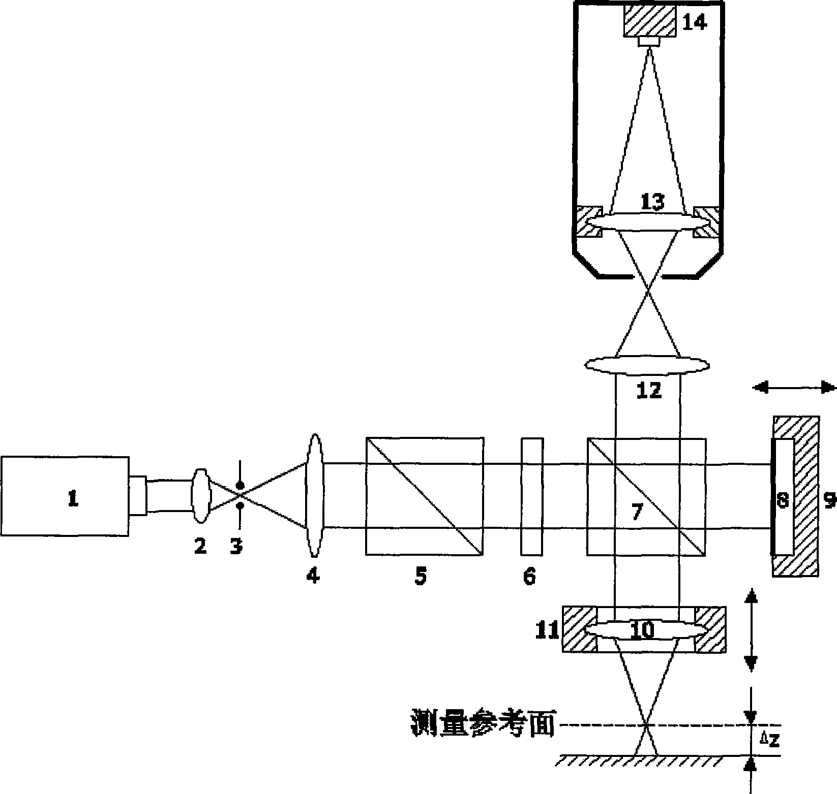
[0019] Phase-shift interference secondary confocal soft pinhole detection device includes: laser 1, focusing objective lens 2, illumination pinhole 3, beam expander collimating objective lens 4, polarization beam splitter 5, quarter wave plate 6, ordinary beam splitter 7 , plane mirror 8, the first micro-driver 9, detection focusing objective lens 10, the second micro-driver 11, collection objective lens 12, described device also comprises microscopic objective lens 13 and CCD camera 14, adjusts microscopic objective lens 13 and CCD camera 14 It is located at the position where the horizontal light spot at the focal plane converging to the collecting objective lens 12 becomes a clear enlarged image, and the soft pinhole detection device is composed of the microscopic objective lens 13 and the CCD camera 14 .

[0020] Working principle: Laser 1 emits li...


PUM


Abstract

The invention relates to a phase-shifting secondary interference confocal soft-pinhole detection device and a method, belonging to the field of measurement of ultra-precise three-dimensional microstructure surface topography. The soft-pinhole detection device comprises a microobjective and a CCD camera. The method comprises the steps: removing a measuring surface, moving the microobjective and the CCD camera to determine the position for collecting a microobjective benchmark focal plane, positioning an Airy spot center on a CCD image surface, intercepting and locking a fixed pixel area with different microscopic magnification times on the CCD image surface as a soft-pinhole, adjusting the microobjective and the CCD camera to display a clear amplified image of a horizontal spot on the position for collecting the microobjective benchmark focal plane, adding the measured surface, and completing the specific micro-displacement measurement by phase-shifting secondary interference confocal measurement. The invention can provide the flexible equivalent pinhole style, effectively reduce alignment errors of the actual confocal pinhole and improve the detection precision of phase-shifting secondary interference confocal spots.

Description

technical field [0001] The invention belongs to the field of ultra-precise three-dimensional microstructure surface topography measurement, and mainly relates to a phase-shifting interference secondary confocal soft pinhole detection device and method. Background technique [0002] The confocal measurement technology was first proposed by M.Minsky in 1957 and obtained the US patent in 1961, the patent number US 3013467. The basic technical idea is to suppress stray light by introducing a pinhole detector to achieve axial tomography capability , At the same time, the horizontal resolution of the confocal microscope is 1.4 times that of the ordinary microscope. After nearly fifty years of development, confocal microscopy has made great progress and progress on the basis of basic confocal, and various types of confocal microscopy devices and technologies have emerged. At present, confocal microscopy measurement technology has been widely used Optics, microelectronics, micromec...

Claims


Application Information

Patent Timeline
Patent Type & Authority Applications(China)
IPC IPC(8): G01B9/02G01B11/02G01B11/24
Inventor 刘俭谭久彬刘涛赵晨光王伟波
Owner HARBIN INST OF TECH
Learn More