
Microchannel heat exchanger and heat exchanging system

A microchannel heat exchanger and heat exchange system technology, applied in the field of heat exchangers, can solve problems such as uneven distribution of gas and liquid, affecting the heat transfer performance of microchannel heat exchangers, etc.

Active Publication Date: 2009-09-02
SANHUA HANGZHOU MICRO CHANNEL HEAT EXCHANGER
View PDF0 Cites 42 Cited by
  • Summary
  • Abstract
  • Description
  • Claims
  • Application Information

AI Technical Summary

Problems solved by technology

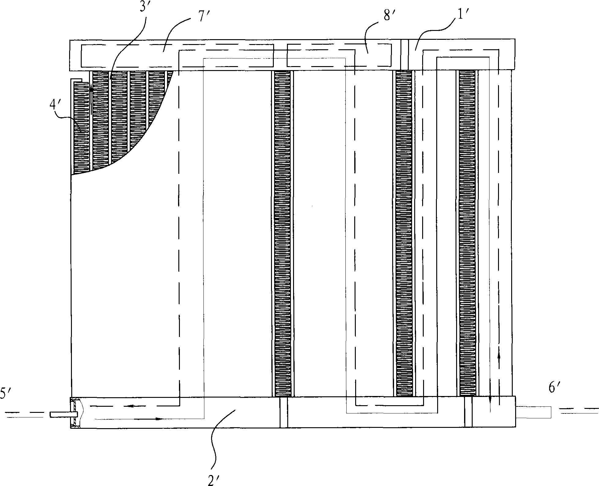
During this process, the refrigerant enters the connecting flow path area 7' in the upper header 1' from the flat tube 3' of the first flow path. The cavity flows to the connecting flow path area 8', and before entering the flat tube 3' of the next flow path, the refrigerant will appear gas-liquid stratification in the middle area 8', which will lead to the flow process of the refrigerant in the next flow path The uneven distribution of gas and liquid in the medium affects the heat transfer performance of the microchannel heat exchanger
Similarly, if figure 1 As shown in , when the refrigerant flows from the second port 6' to the first port 5' ( figure 1 As shown by the dotted line in ), gas-liquid stratification may occur in the connecting flow path area 7', which will affect the heat transfer performance of the microchannel heat exchanger
[0004] In addition, when the microchannel heat exchanger is used as a dual-mode heat exchanger such as a heat pump, the refrigerant needs to flow in both directions, for example, in the cooling mode, the refrigerant flows from the first port 5' to the second port 6', such as figure 1 shown by the solid line in ; while in the heating mode, the refrigerant flows from the second port 6' to the first port 5', as figure 1 As shown by the dotted line in , gas-liquid stratification will occur in the connecting flow path areas 7', 8', thus affecting the heat transfer performance of the microchannel heat exchanger
[0005] Therefore, there is a need to further improve the design of microchannel heat exchangers to reduce the problem of gas-liquid stratification in the header, resulting in reduced heat transfer performance

Method used


Image

  • Microchannel heat exchanger and heat exchanging system
  • Microchannel heat exchanger and heat exchanging system
  • Microchannel heat exchanger and heat exchanging system

Examples


Embodiment Construction

[0049]Embodiments of the present invention are described in detail below, examples of which are shown in the drawings, wherein the same or similar reference numerals designate the same or similar elements or elements having the same or similar functions throughout. The embodiments described below by referring to the figures are exemplary only for explaining the present invention and should not be construed as limiting the present invention.

[0050] In the present invention, the terms "first", "second", etc. are only for convenience of description, and the terms "left, right, top, and bottom" are positional relationships based on the drawings, and are only for convenience of description, and cannot be interpreted. To limit the present invention.

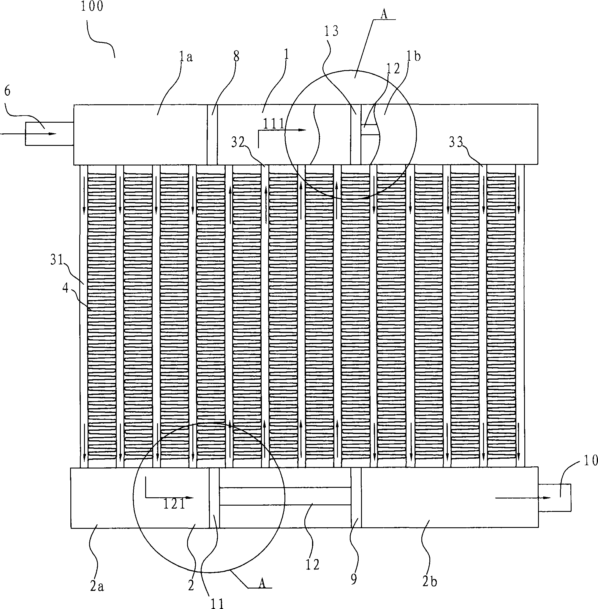
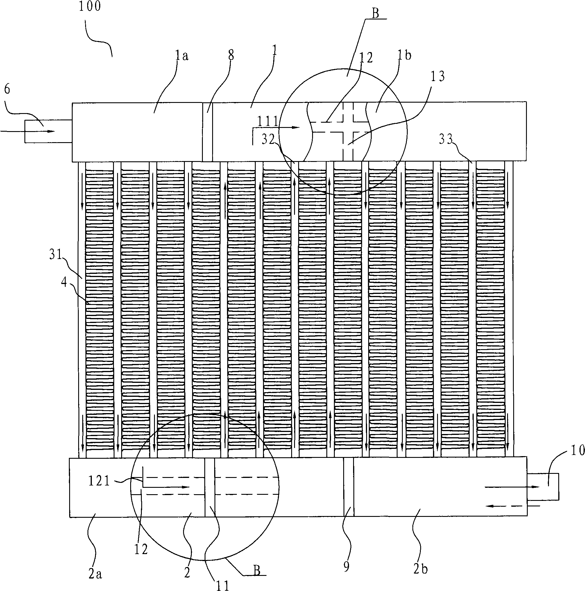
[0051] In addition, the term "flow path" refers to the path of fluid flowing in one direction in the flat tube from one header to the other (such as Figure 2a with 2b A microchannel heat exchanger with 3 flow paths is shown). Whe...


PUM


Abstract

The invention provides a microchannel heat exchanger which comprises a first collecting tube, a second collecting tube, flat tubes and fins. The fins are respectively arranged between adjacent flat tubes; the inside of the first collecting tube and / or the second tube are / is divided into a plurality of chambers by at least one partition member to form a plurality of flow passages in the microchannel heat exchanger; two adjacent flow passages are communicated with each other through one of connection flow passages in the first collecting tube and / or the second collecting tube; and at least one connection passage is internally provided with a second partition member and a distributor which communicates both sides of the second partition member so as to distribute the fluid at one side of the second partition member to the other side of the second partition member. The microchannel heat exchanger can reduce gas-liquid stratification of refrigerant and improve the heat exchanging performance of refrigerant. In addition, the invention also provides the heat exchanging system using the microchannel heat exchanger.

Description

technical field [0001] The invention relates to a heat exchanger, in particular to a microchannel heat exchanger with multiple flow paths and a heat exchange system using the microchannel heat exchanger. Background technique [0002] Microchannel heat exchangers are devices used for heat exchange, such as condensers, evaporators or heat pumps in refrigeration systems. [0003] A conventional microchannel heat exchanger includes a header, flat tubes formed with microchannels, and fins disposed between adjacent flat tubes. In order to improve heat exchange performance, multiple flow paths can be formed inside the heat exchanger. Such as figure 1 As shown, a traditional micro-channel heat exchanger with 4 flow paths is shown. When the micro-channel heat exchanger with multiple flow paths is used as a condenser or evaporator, the refrigerant flows in one direction from the first port 5' to the second port 6' and the refrigerant direction is as figure 1 shown by the solid lin...

Claims


Application Information

Patent Timeline
IPC IPC(8): F28D1/053F28F9/02F28F9/22F25B39/00
Inventor 刘华钊黄宁杰
Owner SANHUA HANGZHOU MICRO CHANNEL HEAT EXCHANGER
Learn More