Deep water hydrocarbon transfer system

A technology of oil and gas mooring, which is applied in the direction of transportation and packaging, special-purpose vessels, ships, etc., and can solve problems such as fast and easy establishment of mechanical and hydraulic connections that have not been pointed out

Inactive Publication Date: 2009-08-26
SINGLE BUOY MOORINGS INC
View PDF1 Cites 11 Cited by
  • Summary
  • Abstract
  • Description
  • Claims
  • Application Information

AI Technical Summary

Problems solved by technology

Known mooring systems are only suitable for water depths of a few hundred meters
Furthermore, no provision is i...

Method used


Image

  • Deep water hydrocarbon transfer system
  • Deep water hydrocarbon transfer system
  • Deep water hydrocarbon transfer system

Examples


Embodiment Construction

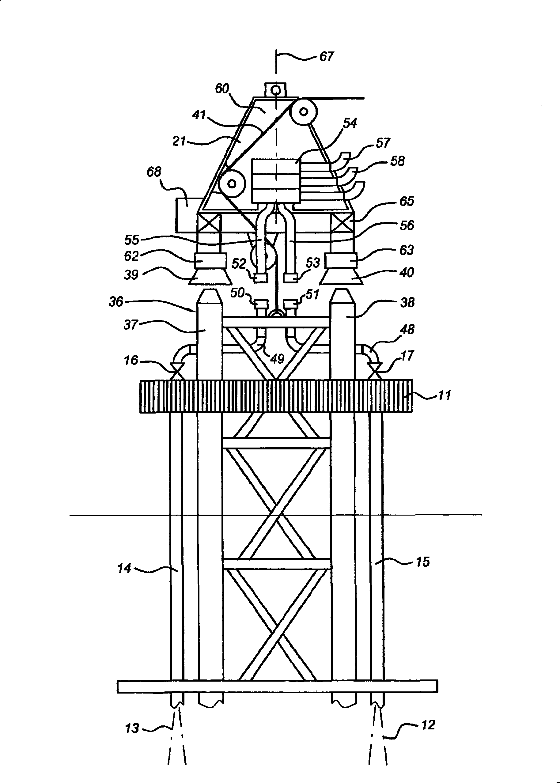
[0027] figure 1 An oil and gas transfer system 1 is shown comprising a mooring buoy 2 and a vessel 3 with a mooring arm 4 . The mooring buoy 2 comprises a plurality of subsea buoyancy members 5 , 6 , 7 and a truss support structure 10 carrying a support platform 11 . Steel risers 12 , 13 are guided from the subsea well to the support platform 11 . The upper half of the risers 12,13 are guided by riser ducts or "I-pipes" 14,15. The risers end in valves 16, 17 near the riser support platform 11, closing each riser. The arm 4 on the vessel 3 carries at its end a connector 21 for mechanical connection to the end of the upper buoy and for extending between the risers 12, 13 and via the connector 21 and the arm 4 to the vessel 3 Provide fluid connections between the pipelines.

[0028] The buoy 2 comprises lateral mooring lines 23, 24, each extending at an angle of approximately 45°, and attaching the buoy to the seabed. The lateral mooring lines limit the pitching and heaving ...


PUM

PropertyMeasurementUnit
Lengthaaaaaaaaaa

Abstract

The invention provides a system composed of a hydrocarbon transfer buoy (2, 82) and a vessel (3, 95), the buoy having a length (H1,H2,H3) of at least 50 m and a length-to-width ratio of at least 10: 1, and comprising a submerged buoyancy member (5,6,7,85) having a length of at least 30 m and being situated at a depth of at least 10 m below water level, a support frame (10,96) being connected to the top of the buoyancy member and projecting above water level, the support frame carrying a support deck (11,91) and a mooring buoy connector (36, 99,102) for attaching to a mooring arm connector (21,100) of the vessel, which mooring arm connector is situated on an arm (4,92) projecting outboard from the vessel's hull, the buoy being anchored to the sea bed via anchor lines (23,24,83,84) which extend at an angle to a vertical direction, at least one hydrocarbon riser (12,13,93,94) being attached to the buoy, the support frame (10, 96) is an open support frame, the buoyancy member being connected to the sea bed via at least one substantially vertical taut tendon (31,32,33).

Description

technical field [0001] The invention relates to a system consisting of an oil and gas transfer buoy having a length of at least 50 meters and a length-to-width ratio of at least 10:1, and a vessel, the buoy comprising: an underwater buoyancy member having a length of at least 30 meters and located in a horizontal plane A depth of at least 10 meters below; an open support frame attached to the top of the buoyancy member and extending above water level, the support frame carrying the support platform and the mooring buoy connectors for attachment to the vessel's mooring arm connectors , the mooring arm connector is located on an arm extending outboard from the hull of the vessel, the buoy is anchored to the seabed by anchor lines extending at an angle to the vertical; and at least one oil and gas riser attached to the buoy. Background technique [0002] Such a system is known from FR 2560549 . The mooring system described in this publication shows a small, elongated buoy to w...

Claims


Application Information

Patent Timeline
IPC IPC(8): B63B22/02
CPCB63B22/026Y10T137/7728B63B22/02
Inventor 杰克·波拉克大卫·刘易斯·汉金
Owner SINGLE BUOY MOORINGS INC
Why Eureka
Try Eureka