Micro electromagnetic energy harvester and a preparation method
An energy harvester, electromagnetic technology, applied in the manufacture of inductors/transformers/magnets, circuits, permanent magnets, etc., can solve the problem of large device size, and achieve the effect of easy packaging, small size, and suitable for mass production
- Summary
- Abstract
- Description
- Claims
- Application Information
AI Technical Summary
Problems solved by technology
Method used
Image

Examples
Embodiment 1
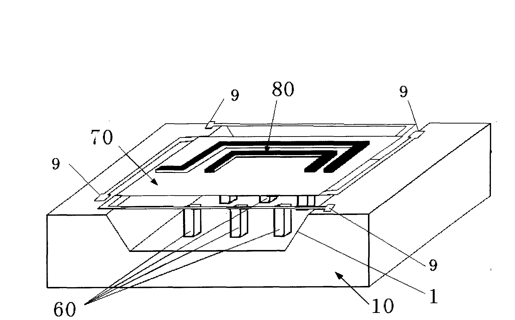
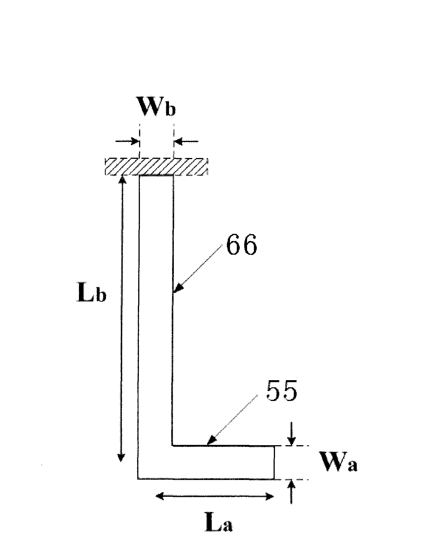
[0038] The miniature electromagnetic energy harvester consists of three main parts: an electroplated permanent magnet 60, a vibrating membrane 70 and a planar helical coil 80, such as figure 1 shown. The V-shaped groove 1 of the silicon wafer is obtained by wet etching the silicon wafer 10. The permanent magnet of the energy harvester of the present invention is realized by the electroplating permanent magnet array 60 located in the V-shaped groove 1 of the silicon wafer. The vibrating film 70 is located on the silicon wafer. The surface of the sheet is facing the electroplated permanent magnet array 60 , and the planar spiral coil 80 is located directly above the vibrating membrane 70 . The vibrating membrane 70 is composed of four crab-like cantilever beams and a vibrating plate, and the crab-like cantilever beams are as image 3 shown. The cantilever beam is connected at four right angles of the vibrating plate, and has the same thickness. During electroplating, the cant...
Embodiment 2
[0053] A method for preparing a miniature electromagnetic energy harvester, using a three-dimensional micromachining method combining bulk silicon and surface micromachining techniques, that is, using bulk silicon micromachining techniques to etch silicon to form V-shaped grooves, and The permanent magnet is electroplated in the groove, and then the vibrating membrane and the planar spiral coil are fabricated by surface micromachining technology.
[0054] Including the following steps:
[0055] (1) Backside alignment symbol creation
[0056] Sputter 100nm metal chromium on the back of the silicon wafer, then throw a 5μm thick positive resist AZ P4620, photolithography, develop, etch the metal chromium with 8% hydrochloric acid, remove the positive resist with acetone, and obtain the back alignment symbol of the metal chromium.
[0057] (2) Fabrication of V-shaped grooves on silicon wafers
[0058] Wet Etching Plasma Enhanced Chemical Vapor Deposition (PECVD) of SiO 2 The et...
Embodiment 3
[0066] A method for preparing a miniature electromagnetic energy harvester, using a three-dimensional micromachining method combining bulk silicon and surface micromachining techniques, that is, using bulk silicon micromachining techniques to etch silicon to form V-shaped grooves, and The permanent magnet is electroplated in the groove, and then the vibrating membrane and the planar spiral coil are fabricated by surface micromachining technology.
[0067] Including the following steps:
[0068] (1) Backside alignment symbol creation
[0069] Sputter 100nm metal chromium on the back of the silicon wafer, then throw a 5μm thick positive resist AZ P4620, photolithography, develop, etch the metal chromium with 8% hydrochloric acid, remove the positive resist with acetone, and obtain the back alignment symbol of the metal chromium.
[0070] (2) Fabrication of V-shaped grooves on silicon wafers
[0071] Wet Etching Plasma Enhanced Chemical Vapor Deposition (PECVD) of SiO 2 The et...
PUM
| Property | Measurement | Unit |
|---|---|---|
| Thickness | aaaaa | aaaaa |
| Length | aaaaa | aaaaa |
| Thickness | aaaaa | aaaaa |
Abstract
Description
Claims
Application Information
 - Generate Ideas
- Intellectual Property
- Life Sciences
- Materials
- Tech Scout
- Unparalleled Data Quality
- Higher Quality Content
- 60% Fewer Hallucinations
Browse by: Latest US Patents, China's latest patents, Technical Efficacy Thesaurus, Application Domain, Technology Topic, Popular Technical Reports.
© 2025 PatSnap. All rights reserved.Legal|Privacy policy|Modern Slavery Act Transparency Statement|Sitemap|About US| Contact US: help@patsnap.com