High-efficiency high power factor charger circuit
A high-power, charger technology, applied in battery circuit devices, current collectors, circuit devices, etc., can solve the problems of low cost circuit power factor and increased efficiency, and achieve the effect of improving efficiency, saving electric energy, and improving power factor
- Summary
- Abstract
- Description
- Claims
- Application Information
AI Technical Summary
Problems solved by technology
Method used
Image
Examples
Embodiment 1
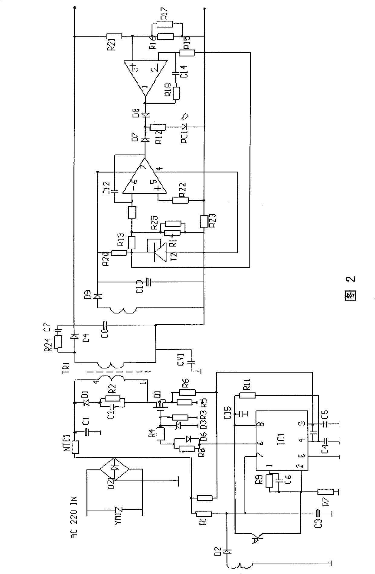
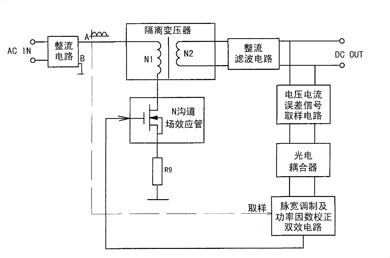
[0031] Embodiment one: see attached image 3 , attached Figure 4 As shown, a charger circuit with high efficiency and high power factor includes a rectifier circuit, a transformer TR1, a rectifier filter circuit, a voltage and current error signal sampling circuit, a photocoupler, a pulse width modulation and power factor correction dual-effect circuit, and an N-channel field field effect transistor Q1.
[0032] The transformer TR1 is a high-frequency transformer, the primary side has one winding which is the first winding N1, and the secondary side has three windings: the second winding N2, the third winding NF and the fourth winding N3. The N-channel field effect transistor Q1 is an N-channel field effect transistor.
[0033] The rectifier circuit is a full-bridge rectifier circuit, and its front part is connected to the AC power frequency power supply through an electromagnetic interference EMI filter link formed by some inductors and capacitors, its output negative term...
PUM
 Abstract
Description
Claims
Application Information
 - R&D
- Intellectual Property
- Life Sciences
- Materials
- Tech Scout
- Unparalleled Data Quality
- Higher Quality Content
- 60% Fewer Hallucinations
Browse by: Latest US Patents, China's latest patents, Technical Efficacy Thesaurus, Application Domain, Technology Topic, Popular Technical Reports.
© 2025 PatSnap. All rights reserved.Legal|Privacy policy|Modern Slavery Act Transparency Statement|Sitemap|About US| Contact US: help@patsnap.com


