
Device for lubricating cylinders

A cylinder block and lubricant technology, applied in the field of cylinder block lubrication devices, can solve problems such as increasing lubricant volume and pollutant accumulation

Inactive Publication Date: 2009-08-26
WAERTSILAE SCHWEIZ AG
View PDF3 Cites 8 Cited by
  • Summary
  • Abstract
  • Description
  • Claims
  • Application Information

AI Technical Summary

Problems solved by technology

However, due to the presence of a certain amount of lubricant in the circuit, it increases the volume of lubricant in the system
And this is also disadvantageous, because by recirculating the lubricant, contaminants may accumulate in the bypass flow

Method used


Image

  • Device for lubricating cylinders
  • Device for lubricating cylinders
  • Device for lubricating cylinders

Examples


Embodiment Construction

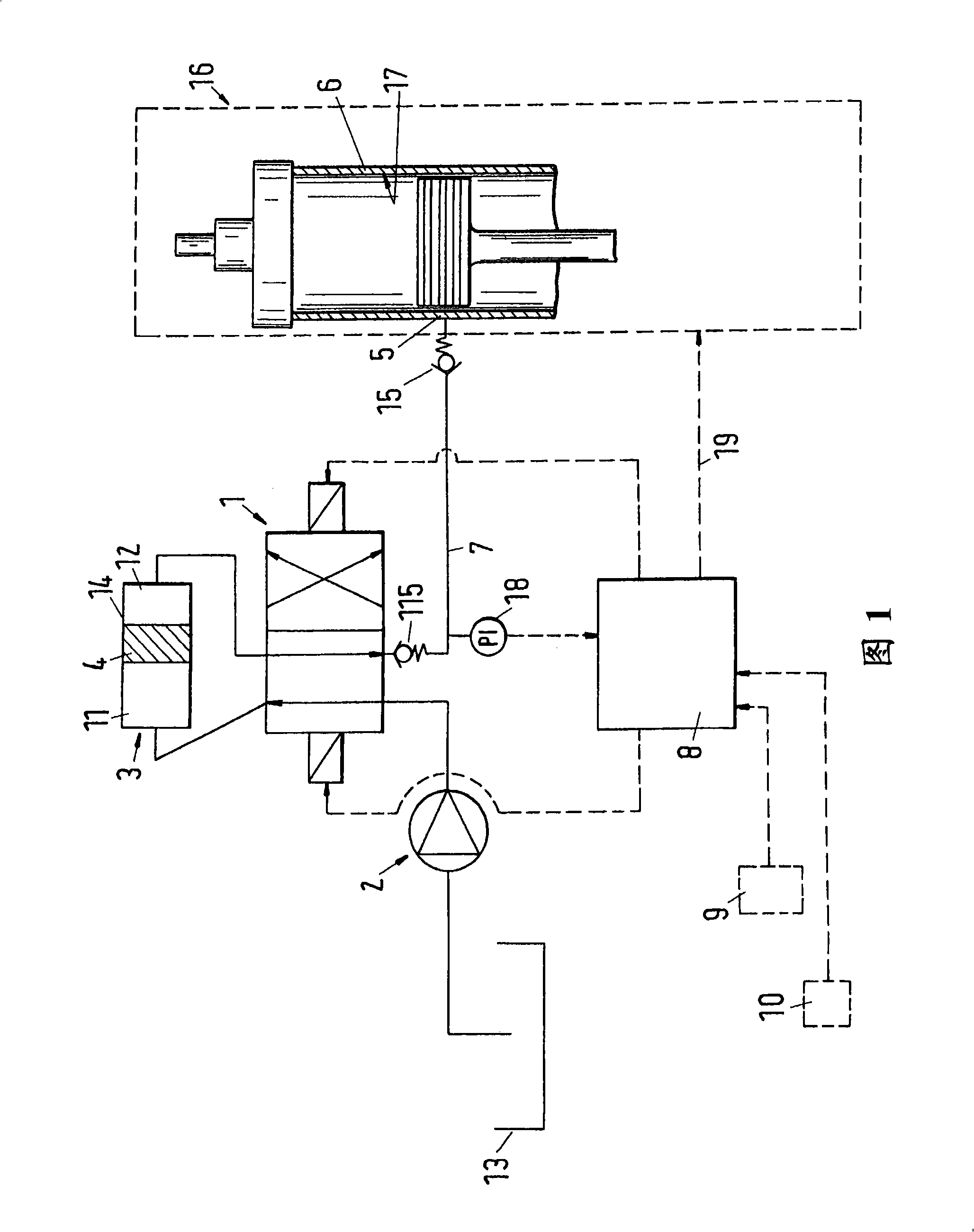
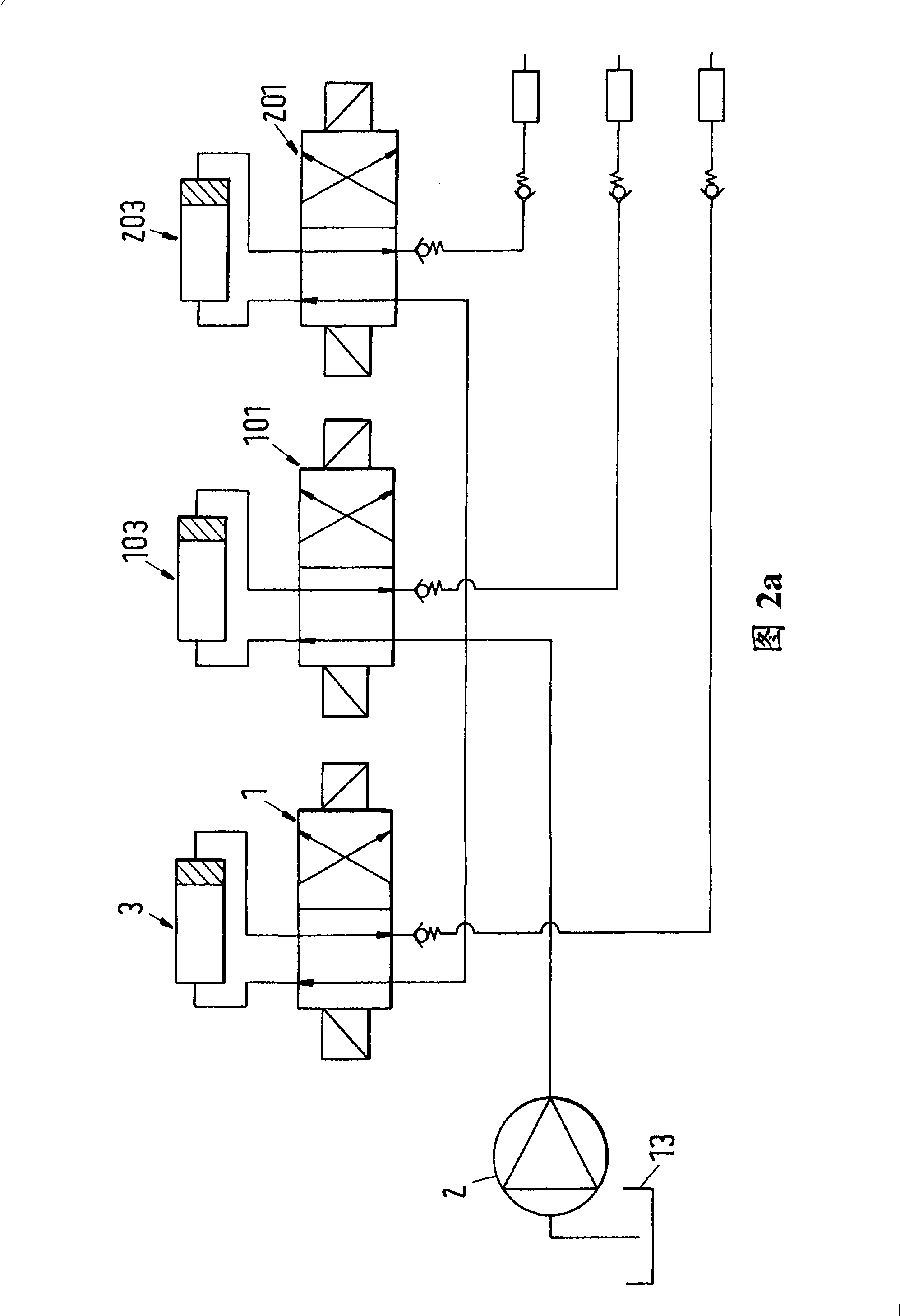
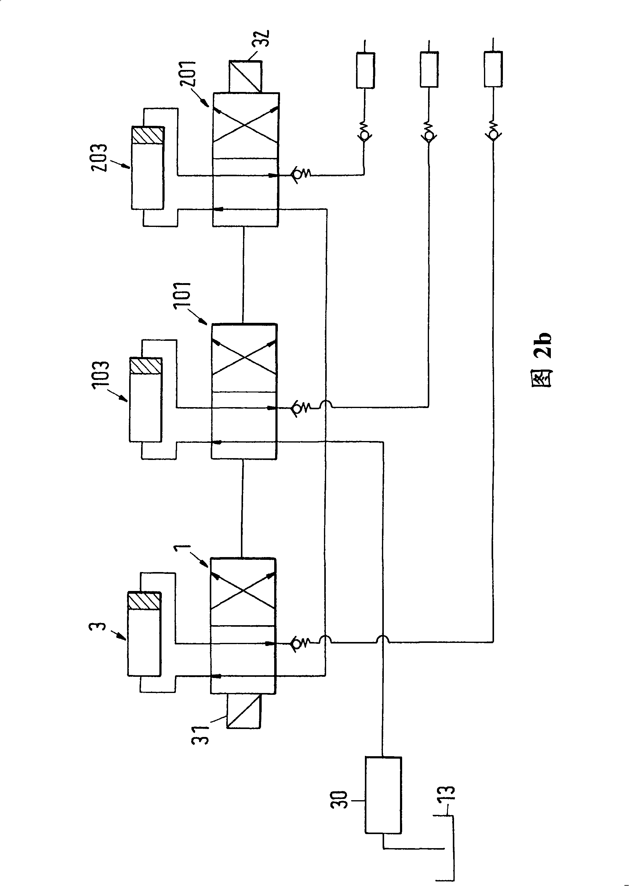
[0036] according to figure 1 The device according to the invention comprises a lubricant source 13 which can be formed as a lubricant reservoir and through which lubricant can be supplied. The supply device 2 is connected to a lubricant source 13 via which lubricant can be supplied from the lubricant source to the consumption mechanism. The lubricant outlet 5 is shown as a consumption mechanism, which may for example comprise a lubricant nozzle through which the lubricant is conveyed to the system to be lubricated, which in the shown case is the cylinder block 6 of the internal combustion engine 16 work surface. As an alternative to the supply means, a common rail reservoir can be provided which already contains lubricant under sufficient pressure so that lubricant can be supplied to the relevant consumer if necessary. Pressurized lubricant is delivered to the first chamber 1 of the piston unit 3 by the pump 2 or from a common rail reservoir. The pressure of the lubricant a...


PUM


Abstract

The invention relates to a device for lubricating cylinders. A device for lubricating a contact surface of the cylinder body of an internal combustion engine comprises a lubricant source making the lubricant available and a lubricant outlet by which the lubricant is applied on the contact surface, wherein the lubricant is conveyed from the lubricant source to the lubricant outlet. A switching element and a piston element are arranged between the lubricant source and the lubricant outlet. The piston unit includes a first chamber and a second chamber separated by a movable piston. The switching element positioned between the lubricant source and the lubricant outlet connects the first chamber or the second chamber with the lubricant outlet.

Description

technical field [0001] The invention relates to a device for lubricating cylinder blocks of internal combustion engines, especially large diesel engines. Background technique [0002] It is known from the prior art to provide a hydraulically driven pump in the lubricant supply line, by means of which the lubricant is supplied onto the working surfaces of the cylinder block of the internal combustion engine. The cost and complexity associated with the operation of a hydraulic pump is relatively high because the pump is connected to a hydraulic fluid circuit which must be kept separate from the lubricant circuit since hydraulic fluid and lubricant are not allowed to mix during operation. Pumps must build pressure, especially for units used in large diesel engines. In order to support the pump during its operation, it is proposed in the prior art according to DE 199 59 300 A1 to provide a discharge mechanism with an associated actuating mechanism between the pump and the lubri...

Claims


Application Information

Patent Timeline
IPC IPC(8): F01M1/04F01M1/16F01M11/00
CPCF01M1/16F01M1/08F16N25/02F01M2001/083F01M1/14F01M1/06F02F1/20F02F1/16F02F1/02
Inventor O·克里斯滕森
Owner WAERTSILAE SCHWEIZ AG
Learn More