
Novel power supplying system using electric railway direct feeding system of outdoor modularized electric device

A technology for electrified railways and power supply, applied in power lines, overhead lines, transportation and packaging, etc., can solve the problems of high investment cost, troublesome maintenance, large floor space, etc., achieve high degree of factory manufacturing and short construction period , the effect of reducing the floor space

Active Publication Date: 2009-08-19
CHINA RAILWAY SHANGHAI DESIGN INST GRP +1
View PDF0 Cites 19 Cited by
  • Summary
  • Abstract
  • Description
  • Claims
  • Application Information

AI Technical Summary

Problems solved by technology

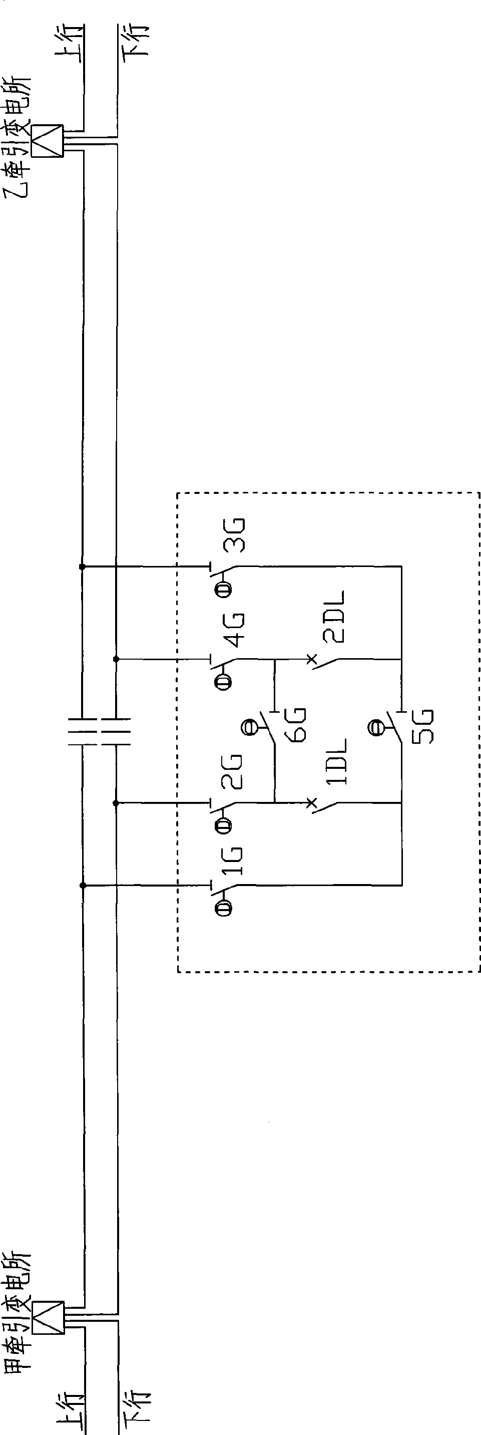
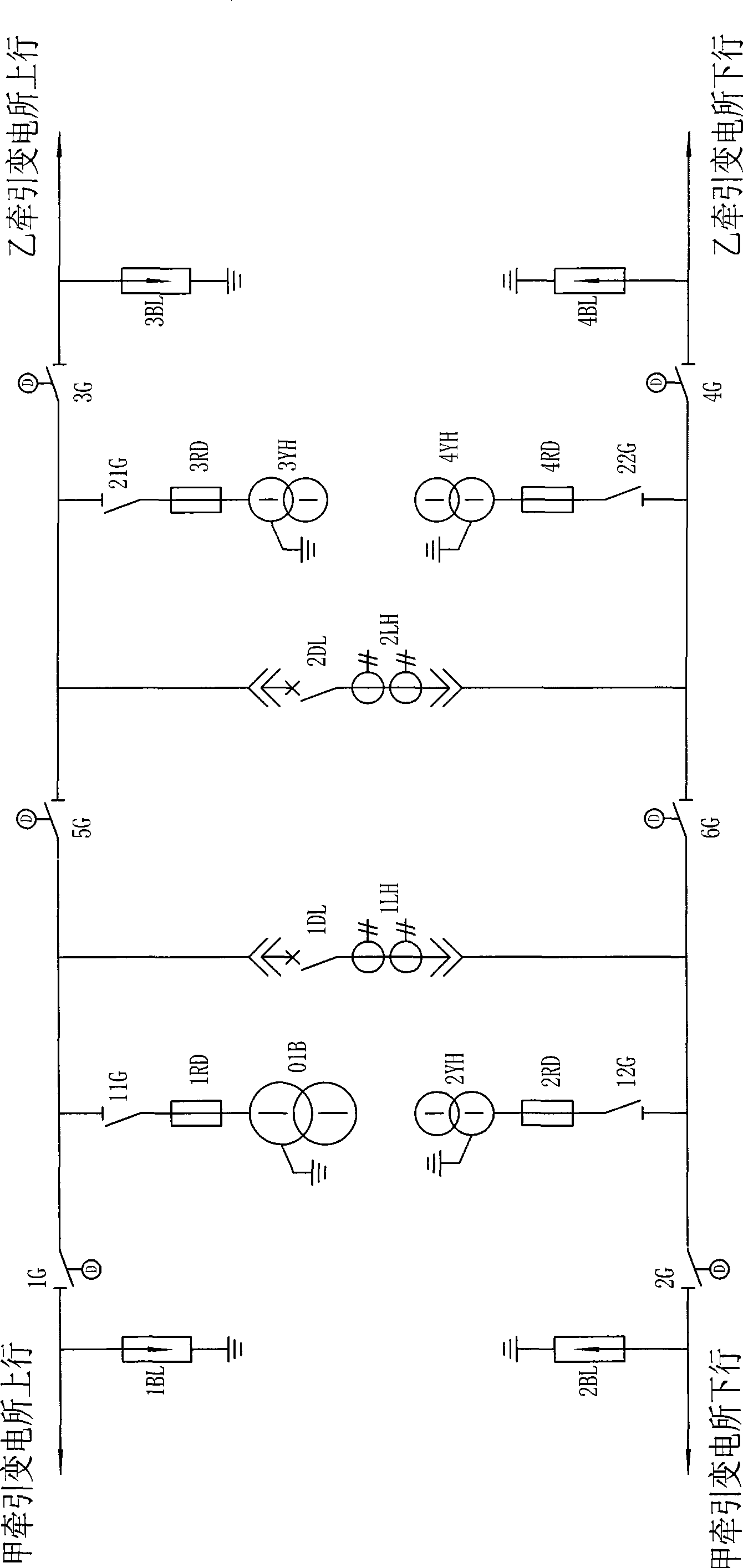
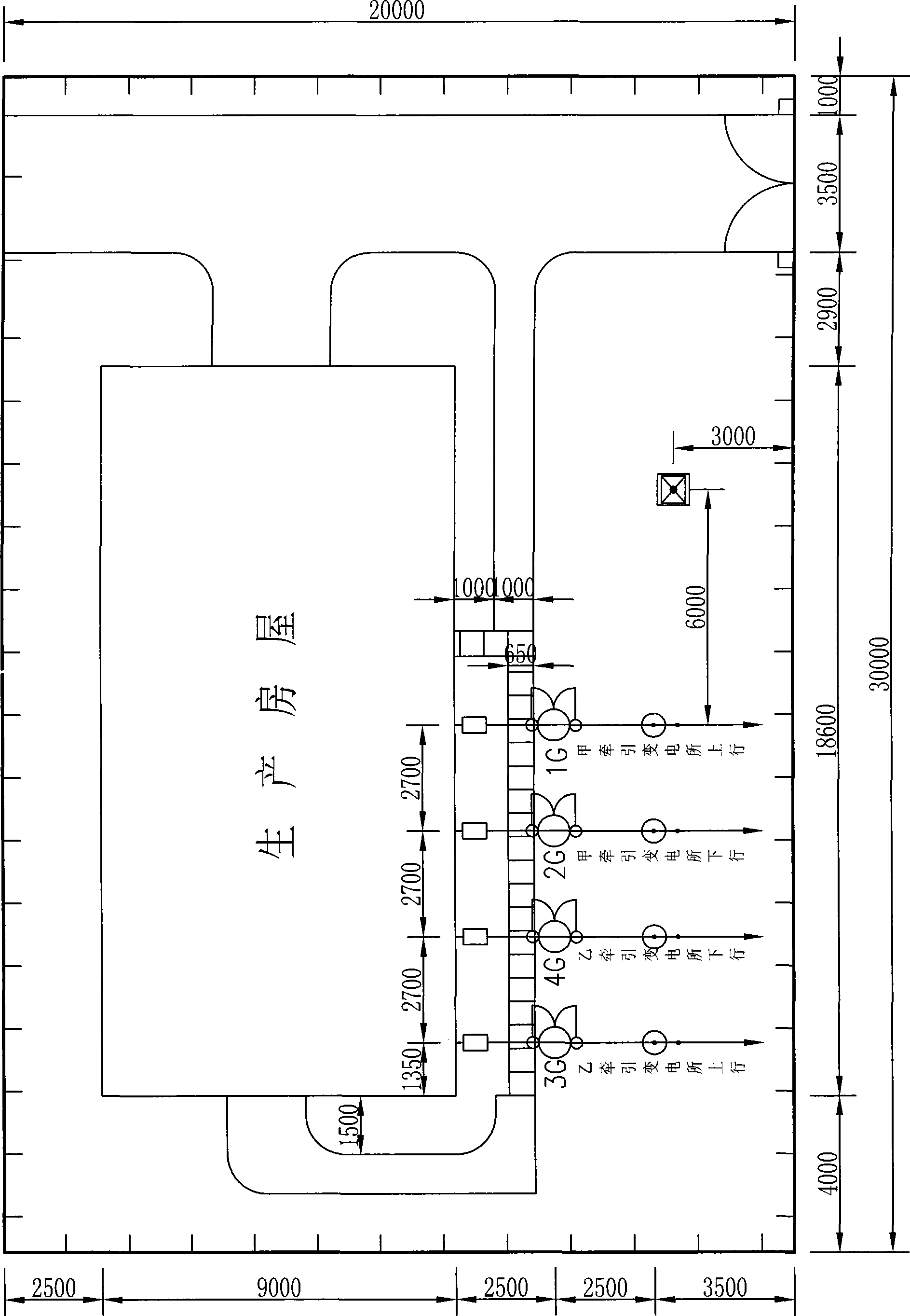
[0035] In order to overcome the shortcomings of the existing power supply system of the 27.5kV traction network of electrified railways, which have a large footprint, high investment costs, and troublesome maintenance, the present invention provides a land that is required for traction and substation (the area of ​​the land to be occupied is larger than the existing one) Some are small), but other equipment layouts do not require a dedicated site; and reduce investment costs, have high reliability, maintenance-free, high degree of factory manufacturing, and short construction period for direct power supply of electrified railways using outdoor modular appliances new power supply system

Method used


Image

  • Novel power supplying system using electric railway direct feeding system of outdoor modularized electric device
  • Novel power supplying system using electric railway direct feeding system of outdoor modularized electric device
  • Novel power supplying system using electric railway direct feeding system of outdoor modularized electric device

Examples


Embodiment Construction

[0072] The present invention will be further described below in conjunction with the accompanying drawings.

[0073] refer to Figure 8 ~ Figure 13, a new type of power supply system for electrified railway direct power supply using outdoor modular appliances, including a traction substation arranged on the side of the electrified railway, the output side of the traction substation is connected to the up / down catenary, and the Parallel equipment with parallel power supply function is provided between the power supply arm ends of the up / down catenary of two adjacent traction substations, and at the power supply arm ends of the up / down catenary of two adjacent traction substations There are over-area equipment with over-area power supply function in the sub-phase, and switching equipment with segmented or partitioned power supply functions are arranged between the up / down catenary and the feeder end. The up / down catenary passes through two The power connection isolating switch ...


PUM


Abstract

The invention discloses a novel power supply system applying an electrified railway of an outdoor modularized electric appliance to directly supply power, which comprises a traction substation, wherein the output side of the traction substation is connected with an uplink / downlink contact net; parallel equipment and skip zone equipment are arranged between tail ends of power supply arms of uplink / downlink contact nets of two adjacent traction substations; opening and closing equipment is arranged between the uplink / downlink contact nets and the feeder ends; the uplink / downlink contact nets are connected with the opening and closing equipment through two electric isolating switches; the opening and closing equipment is connected with two feeder ends through two internet insolating switches; the parallel equipment comprises a first parallel power supply unit and a second parallel power supply unit; the skip zone equipment comprises a first skip zone power supply unit and a second skip zone power supply unit; the two parallel power supply units are parallel modularized electric appliances for power supply; and the opening and closing equipment comprises four modularized electric appliances for opening and closing. The system has little floor area, reduces investment cost, and has high reliability, non maintenance, high industrial manufacturing degree and short construction period.

Description

technical field [0001] The invention relates to a traction power supply system of direct power supply mode for electrified railways. Background technique [0002] At present, the traction power supply system in the direct power supply mode of electrified railways at home and abroad is mainly composed of traction substations, divisional substations, switching stations, and catenary. [0003] The parallel power supply method in which the end of the power supply arm passes through the partition station is generally adopted (see details for details) figure 1 ); when the traction network needs to be segmented (or partitioned), switching stations can be set up to realize segmented (or partitioned) power supply; in hubs, large passenger stations and section stations, in order to facilitate power supply and maintenance needs According to the different power supply zones of the electrified channel group, split power supply is implemented. [0004] 27.5kV divisions: the existing div...

Claims


Application Information

Patent Timeline
IPC IPC(8): B60M3/00B60M3/04B60M1/18
Inventor 余家华张北斗
Owner CHINA RAILWAY SHANGHAI DESIGN INST GRP
Learn More