
LED light modulating apparatus suitable for light modulator

A technology of dimming device and LED light source, which is applied to lighting devices, light sources, electric light sources, etc., can solve the problem of inability to adjust the brightness of LED bulbs, and achieve the effects of simple and exquisite design, good dimming effect and long service life.

Inactive Publication Date: 2009-08-12
CIVILIGHT SHENZHEN SEMICON LIGHTING
View PDF0 Cites 35 Cited by
  • Summary
  • Abstract
  • Description
  • Claims
  • Application Information

AI Technical Summary

Problems solved by technology

Therefore, in the prior art, dimmers cannot adjust the brightness of LED bulbs with built-in or external switching power supplies.

Method used

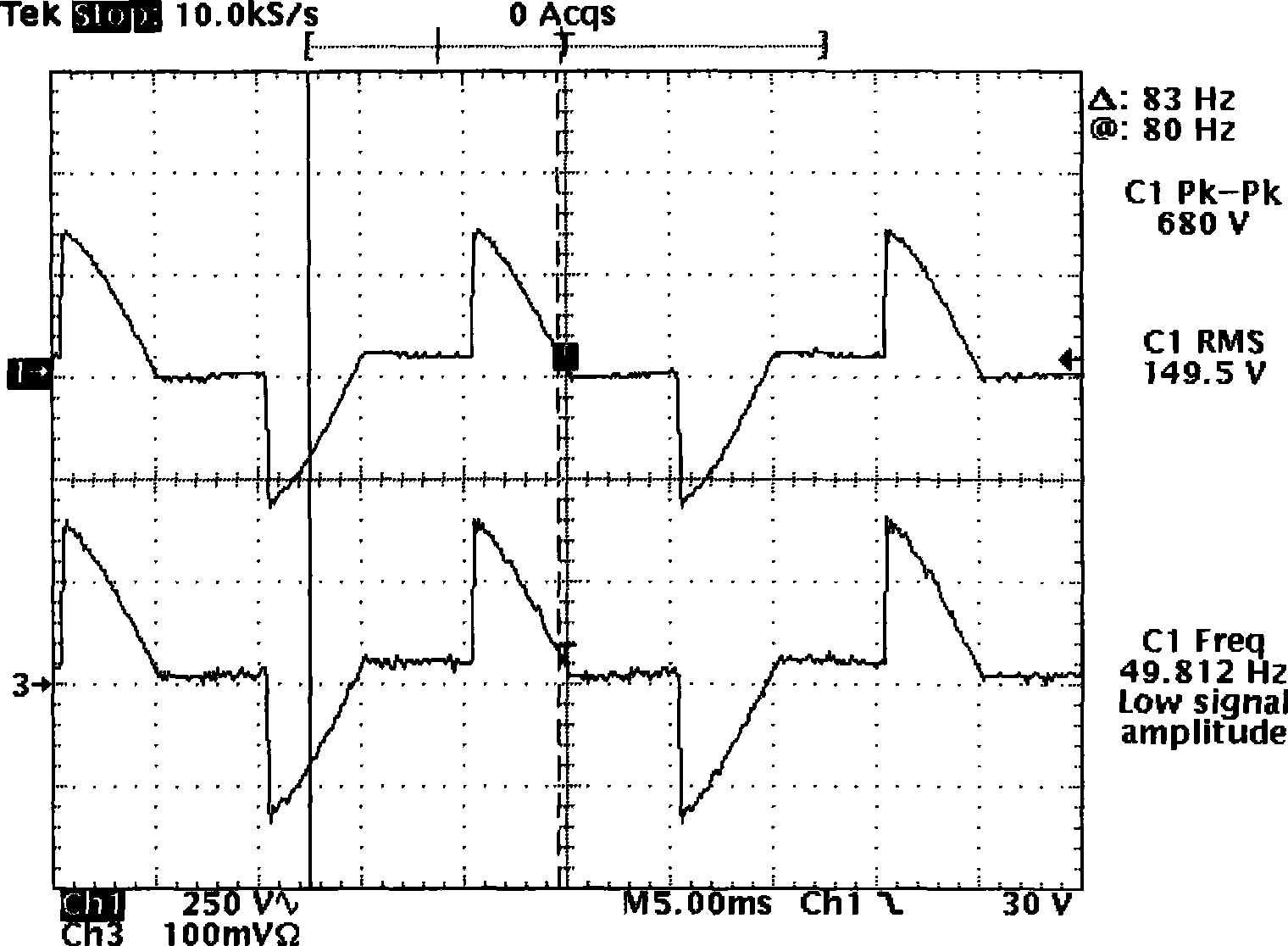
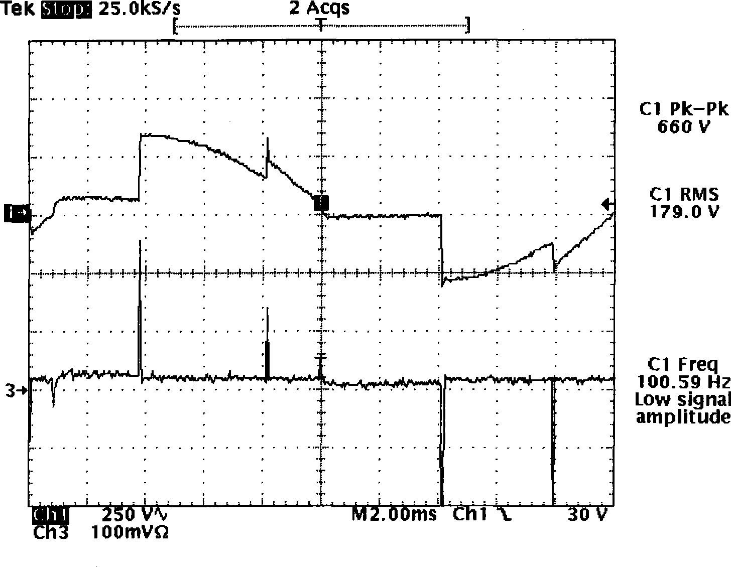

Image

  • LED light modulating apparatus suitable for light modulator
  • LED light modulating apparatus suitable for light modulator
  • LED light modulating apparatus suitable for light modulator

Examples


Embodiment Construction

[0036] In an embodiment of an LED dimming device suitable for a dimmer of the present invention, as Figure 4 and Figure 5 As shown, the voltage of the mains power after phase-cutting by the dimmer is converted into a DC voltage by the primary rectifier 1 and the filter capacitor 2, and the starting resistor 9 first supplies power to the main control chip 10, thereby driving the booster devices 5, 6 and 7 to perform Boost works. The voltages detected by the front-stage voltage detection circuits 3, 4 and the rear-stage voltage detection circuits 11, 12 are simultaneously input to the integrated comparator inside the main control chip 10 for comparison, and then the field effect transistor (MOSFET) driving the booster device is adjusted. The duty cycle of 7 ensures that the voltage of the boost filter capacitor 8 is always 30 volts higher than the voltage of the filter capacitor 2. And the peak current of the dimmer is lower, and the conduction time is exactly the same as th...


PUM


Abstract

The invention relates to an LED dimming device for a dimmer, which comprises a rectifier, a booster, a preamp voltage detecting circuit and a post voltage detecting circuit, a main control chip, a primary transformer, a secondary transformer, a secondary rectification and secondary filter circuit, and a diode switch. The LED dimming device for the dimmer can realize the brightness control of an LED bulb by using a controlled silicon dimmer and a transistor dimmer, and make the use of the energy-saving and environment-friendly LED more widely.

Description

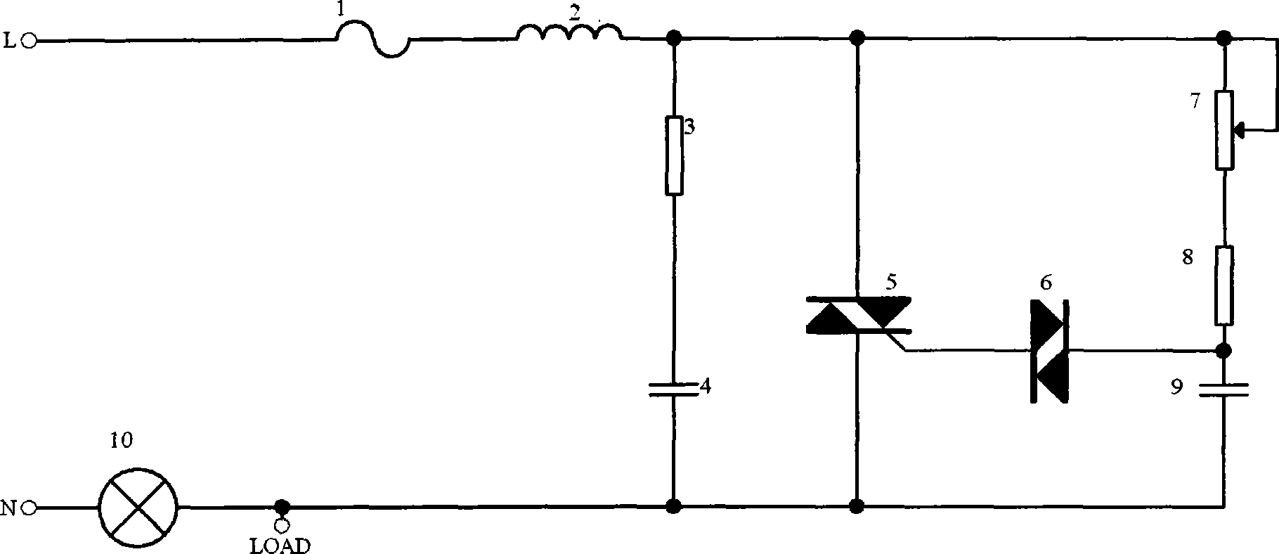
technical field [0001] The invention relates to a dimming device, in particular to an LED dimming device suitable for a dimmer. Background technique [0002] In the prior art, thyristor dimmers and electronic transistor dimmers (hereinafter referred to as "dimmers") can adjust the brightness of traditional tungsten bulbs, see figure 1 , the conduction time of the dimmer 5 is determined by the charging time of the capacitor 9 of the circuit, thereby changing the conduction angle of the sine wave of the alternating current, changing the current of the tungsten filament bulb 10, and achieving the brightness adjustment effect, also known as For cutting-edge phase cutting technology. like figure 1 As shown, the dimmer 5 is connected in series with the tungsten filament bulb 10. When the power supply is connected to the first moment, the current passes through the fuse 1, the inductor 2, the adjustable potentiometer 7, the resistor 8, the capacitor 9, and the tungsten filament b...

Claims


Application Information

Patent Timeline
Patent Type & Authority Applications(China)
IPC IPC(8): H05B37/02H02M7/06
CPCY02B20/40
Inventor 邹德志
Owner CIVILIGHT SHENZHEN SEMICON LIGHTING
Learn More