
Wheel type conveying line

A conveyor line, wheeled technology, applied in the direction of conveyor objects, transportation and packaging, roller tables, etc., can solve the problems of high maintenance cost, easy to wear, and reduced fit tightness, to ensure safety and stability. , Avoid overload damage, absorb the effect of cumulative error

Pending Publication Date: 2019-07-16
SUZHOU GP LOGISTICS SYST
View PDF5 Cites 17 Cited by
  • Summary
  • Abstract
  • Description
  • Claims
  • Application Information

AI Technical Summary

Problems solved by technology

[0004] The problem with this structure is that; on the one hand, due to the continuous friction between the driving roller and the ball or wheel, the surfaces in contact with them are prone to wear, resulting in a decrease in the tightness of the two, and even the surface of the driving roller and the ball or wheel The problem of ineffective contact; on the other hand, the installation accuracy will also cause insufficient contact between the driving roller and the ball or wheel, which leads to the inability of the ball or wheel to be effectively driven to rotate, which seriously affects the effectiveness and stability of the conveying sex
[0005] In addition, in the existing drive structure that drives the deflection wheel to rotate horizontally, the synchronous wheel and synchronous belt transmission or gear transmission are often used, but in the synchronous belt and synchronous wheel transmission mode, the synchronous belt is prone to breakage due to long-term use. The situation affects the stability and service life of the equipment, and the installation of the synchronous belt requires a certain space requirement, which increases the design difficulty of other structures, and at the same time the maintenance cost is high; while the gear transmission method requires multiple gears to mesh, And through the transmission of multiple transmission rods, the consistency of action between multiple transmission rods is often not guaranteed, and the gears are prone to tooth skipping. Once the tooth skipping occurs, the deflection ball in a certain area will not be able to deflect, causing the entire conveying The work of the line fails, which seriously affects the stability of the conveying

Method used

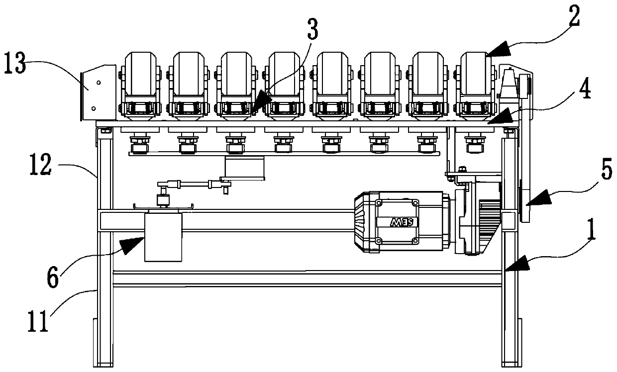
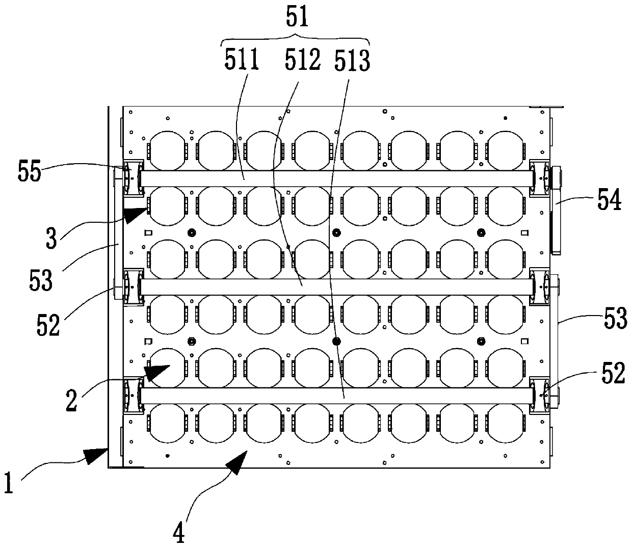
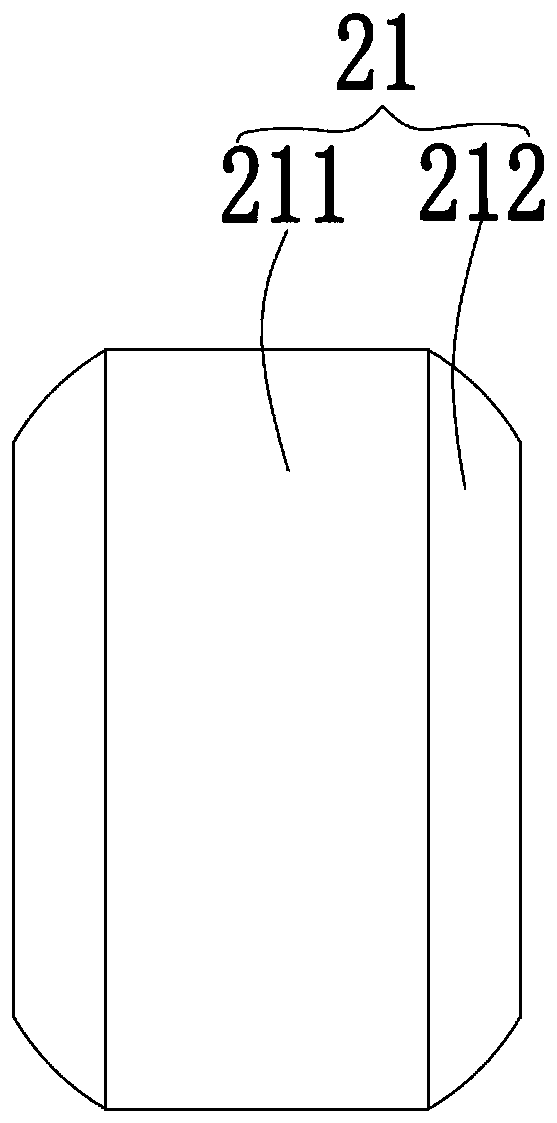

Image

  • Wheel type conveying line
  • Wheel type conveying line
  • Wheel type conveying line

Examples


Embodiment Construction

[0034] Objects, advantages and features of the present invention will be illustrated and explained by the following non-limiting description of preferred embodiments. These embodiments are only typical examples of applying the technical solutions of the present invention, and all technical solutions formed by adopting equivalent replacements or equivalent transformations fall within the protection scope of the present invention.

[0035] In the description of the scheme, it should be noted that the terms "center", "upper", "lower", "left", "right", "front", "rear", "vertical", "horizontal", " The orientation or positional relationship indicated by "inner", "outer", etc. is based on the orientation or positional relationship shown in the drawings, and is only for the convenience of description and simplification of description, rather than indicating or implying that the device or element referred to must have a specific orientation , constructed and operated in a particular or...


PUM


Abstract

The invention discloses a wheel type conveying line which comprises a rack. Multiple rows of eccentric rotating wheels are arranged on the rack in an equal height manner. The axes of all the eccentricrotating wheels are parallel to one another and are parallel to the horizontal plane. Each eccentric rotating wheel is arranged on an installing frame located on the rack in the manner of rotating around the axis of the eccentric rotating wheel. The eccentric rotating wheels on each row are attached to a driving roller, the driving roller makes contact with the lower semicircle of each eccentricrotating wheel, the driving roller is affected by upward elastic force, and thus the eccentric rotating wheels are attached to the driving roller in a self-adapting manner, or the driving roller makescontact with the upper semicircle of each eccentric rotating wheel, the eccentric rotating wheels are affected by the upward elastic force, and the eccentric rotating wheels are attached to the driving roller in a self-adapting manner. The driving roller rotates under the driving of a first power source, and the eccentric rotating wheels are driven to rotate through friction force. According to the wheel type conveying line, the design of the scheme is elaborate, the eccentric rotating wheels or the driving roller are affected by the upward elastic force, thus the eccentric rotating wheels always keep being attached to the driving roller, after abrasion is caused or when the installing position precision is poor, self-adaptive adjusting is achieved, rotating between the eccentric rotatingwheels and the driving roller is effectively ensured, and the conveying stability is improved.

Description

technical field [0001] The invention relates to the field of conveying equipment, especially a wheeled conveying line. Background technique [0002] At present, there are many types of sorting machines, and the sorting efficiency of different sorting machines varies greatly. Common automatic sorting machines include belt conveyors, roller conveyors, cross-belt sorting, slider sorting, and deflection sorting. wheel sorting etc. [0003] Among them, the deflection wheel feeder is a kind of equipment that realizes the conveyance and steering of objects on it through the rotation and horizontal rotation of multiple independent spheres or wheels. One of the existing driving methods for the rotation of spheres or wheels is friction drive. , that is, the driving roller is in contact with the sphere or wheel, and the driving roller rotates and drives the rotation of the sphere or wheel through friction. [0004] The problem with this structure is that; on the one hand, due to the ...

Claims


Application Information

Patent Timeline
Patent Type & Authority Applications(China)
IPC IPC(8): B65G13/07B65G47/71
CPCB65G13/07B65G47/71
Inventor 蔡熙李凯
Owner SUZHOU GP LOGISTICS SYST
Learn More