
Electric power facilities theft monitoring method and monitor thereof

A technology for power facilities and monitors, applied in the direction of anti-theft alarms, instruments, alarms, etc., can solve the problems of high implementation requirements, high construction costs, easy to be struck by lightning, etc., and achieves strong operability, low implementation cost, and convenient use. Effect

Inactive Publication Date: 2009-08-12
CHINA MOBILE GROUP ZHEJIANG +1
View PDF4 Cites 8 Cited by
  • Summary
  • Abstract
  • Description
  • Claims
  • Application Information

AI Technical Summary

Problems solved by technology

There are also some schemes that install large impedance inductors and DC power supplies on the power lines and detect on-resistance to detect whether there is a theft. These schemes have high implementation requirements and many false alarms
There are also some measures that are attached to the line sensor, such as a detection signal line attached to the cable. When the cable is cut by a thief, the detection signal line is also broken to realize the function of monitoring theft. The detection signal line is generally laid together with the cable, or customized In cables, these measures are costly to construct, inconvenient to implement, vulnerable to lightning strikes, and poor in reliability

Method used


Image

  • Electric power facilities theft monitoring method and monitor thereof
  • Electric power facilities theft monitoring method and monitor thereof
  • Electric power facilities theft monitoring method and monitor thereof

Examples


Embodiment Construction

[0014] The preferred embodiments of the present invention will now be described in detail in conjunction with the accompanying drawings.

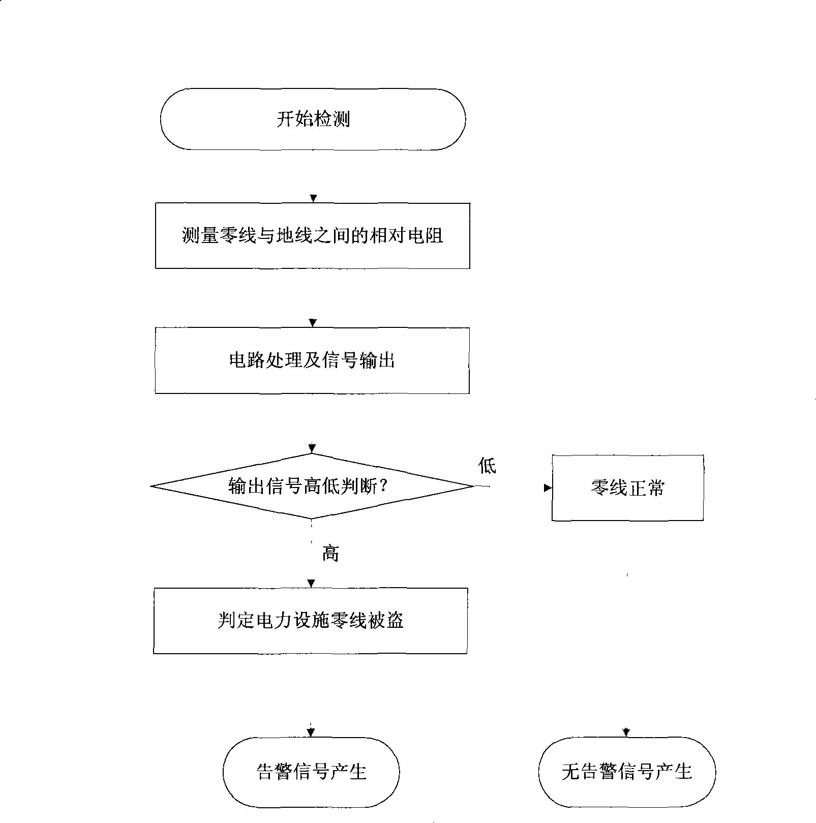
[0015] see figure 1 The power facility theft monitoring method shown includes the following steps: using a sensor to measure the relative resistance between the neutral wire and the ground wire; performing circuit processing on the collected relative resistance, and outputting an on-off state judging signal; judging according to the on-off state The high and low state of the signal judges whether the zero line is stolen. If the on-off state judgment signal is high, it is determined that the zero line is stolen, and an alarm message is generated. If the on-off state judgment signal is low, it is judged to be normal, and no alarm message is generated.

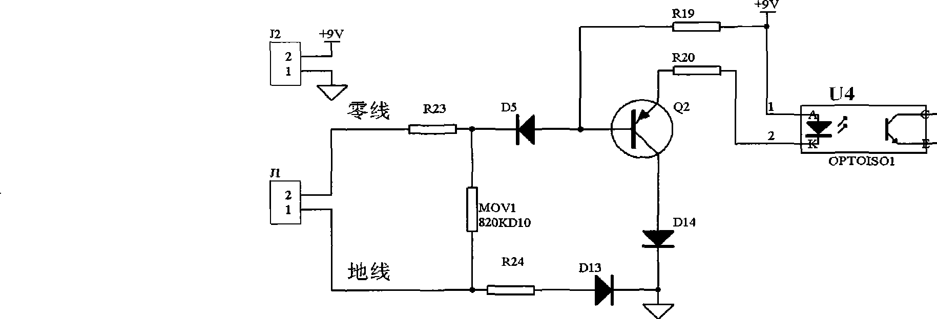
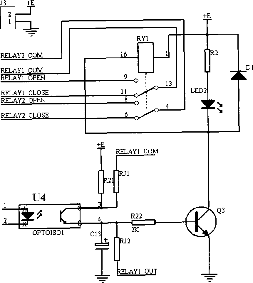
[0016] In the power facility theft monitor of the present invention, the circuit principle diagram of the signal acquisition module and the photoelectric isolation module is as follows: figu...


PUM


Abstract

The invention discloses a theft monitoring method and a monitor by the method for low-voltage electrical installations such as cables, transformers and the like, and belongs to the technical field of antitheft. The electrical installation theft monitoring method comprises the following steps: measuring relative resistance between a zero line and an earth wire; and judging the size of the resistance, generating theft alarm information if the resistance is in the resistance range under the condition of open circuit of the zero line, otherwise not alarming. The electrical installation theft monitor comprises a signal acquisition module which is provided with a zero line interface and an earth wire interface and is used for measuring zero line resistance to the earth to generate on / off state signals of the zero line. The method is simple, has high operability and high accuracy of 100 percent, and can realize low cost.

Description

technical field [0001] The invention belongs to the technical field of anti-theft, and in particular relates to a method for monitoring theft of low-voltage power facilities such as cables and transformers and a monitor thereof. Background technique [0002] In recent years, the frequent theft of low-voltage power facilities such as cables and transformers has seriously affected the safe operation of communication base stations. Technical solutions. [0003] Some existing power facility theft monitoring measures are to add signal transmitters and receivers on the power line, such as installing a signal transmitter at one place of the cable, and installing a signal receiver at another place. When the cable is cut by a thief, the signal is broken. , In order to monitor whether there is a theft situation, these measures have a large investment cost, are inconvenient to implement, are vulnerable to lightning strikes, have poor stability, and poor reliability. There are also so...

Claims


Application Information

Patent Timeline
IPC IPC(8): G01R27/00G08B13/00G08B13/12
Inventor 金美华俞龙云林啸徐日正罗水亮艾锋罗洪钦刘双广
Owner CHINA MOBILE GROUP ZHEJIANG
Learn More